2-12
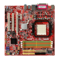
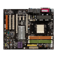
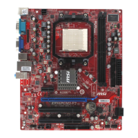
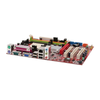
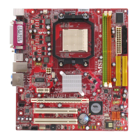
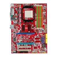
MS-7252 Mainboard
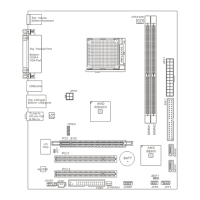
Connectors
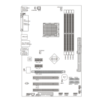
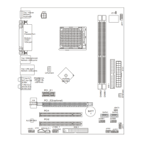
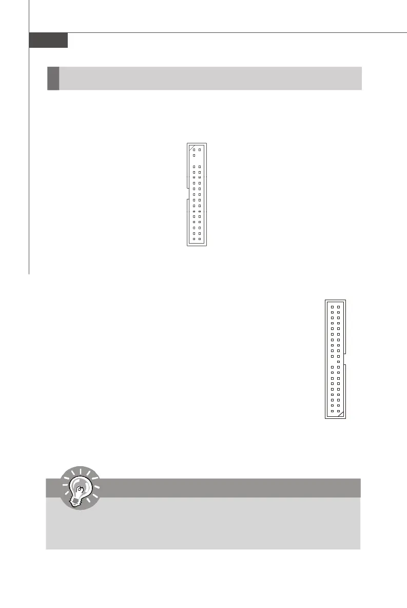
Floppy Disk Drive Connector: FDD1
This standard FDD connector supports 360K, 720K, 1.2M, 1.44M and 2.88M floppy
disk types.
FDD1
IDE1 (Primary IDE Connector)
The first hard drive should always be connected to IDE1. IDE1 can
connect a Master and a Slave drive. You must configure the second
hard drive to Slave mode by setting the jumper accordingly.
IDE2 (Secondary IDE Connector)
IDE2 can also connect a Master and a Slave drive.
IDE1/ IDE2
ATA133 Hard Disk Connectors: IDE1/ IDE2
The mainboard has a 32-bit Enhanced PCI IDE and Ultra DMA 66/100/133
controller that provides PIO mode 0~4, Bus Master, and Ultra DMA 66/
100/133 function. You can connect hard disk drives, CD-ROM and other
IDE devices.
The Ultra ATA133 interface boosts data transfer rates between the
computer and the hard drive up to 133 megabytes (MB) per second. The
new interface is one-third faster than earlier record-breaking Ultra ATA/
100 technology and is backwards compatible with the existing Ultra ATA
interface.
Important
If you install two hard disks on cable, you must configure the second drive to
Slave mode by setting its jumper. Refer to the hard disk documentation
supplied by hard disk vendors for jumper setting instructions.
 Loading...