2-15
Hardware Setup
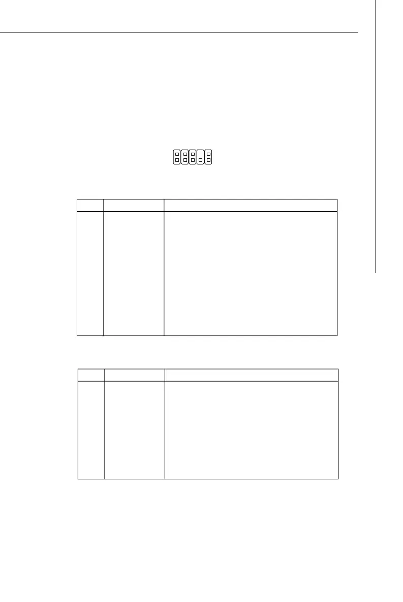
Front Panel Audio Connector: JAUD1
The JAUD1 front panel audio connector allows you to connect the front panel audio
and is compliant with Intel
®
Front Panel I/O Connectivity Design Guide (either HD Audio
or AC’97 Audio).
JAUD1
1
2
9
10
PIN SIGNAL DESCRIPTION
1 MIC_L Microphone - Left channel
2 GND Ground
3 MIC_R Microphone - Right channel
4 PRESENCE# Active low signal-signals BIOS that a High Definition Audio dongle
is connected to the analog header. PRESENCE# = 0 when a
High Definition Audio dongle is connected
5 LINE out_R Analog Port - Right channel
6 MIC_JD Jack detection return from front panel microphone JACK1
7 Front_JD Jack detection sense line from the High Definition Audio CODEC
jack detection resistor network
8 NC No control
9 LINE out_L Analog Port - Left channel
10 LINEout_JD Jack detection return from front panel JACK2
HD Audio Pin Definition
PIN SIGNAL DESCRIPTION
1 MIC Microphone input signal
2 GND Ground
3 MIC_PWR Microphone power
4 NC No Control
5 LINE out_R Right channel audio signal to front panel
6 NC No Control
7 NC No Control
8 Key No pin
9 LINE out_L Left channel audio signal to front panel
10 NC No Control
AC’97 Audio Pin Definition
 Loading...