2-11
Hardware Setup
Fan Power Connector: CPU_FAN1
The fan power connector supports system cooling fan with +12V. When connecting
the wire to the connectors, always take note that the red wire is the positive and
should be connected to the +12V, the black wire is Ground and should be connected
to GND. If the mainboard has a System Hardware Monitor chipset on-board, you must
use a specially designed fan with speed sensor to take advantage of the CPU fan
control.
Important
Please refer to the recommended CPU fans at Intel
®
official website or consult
the vendors for proper CPU cooling fan.
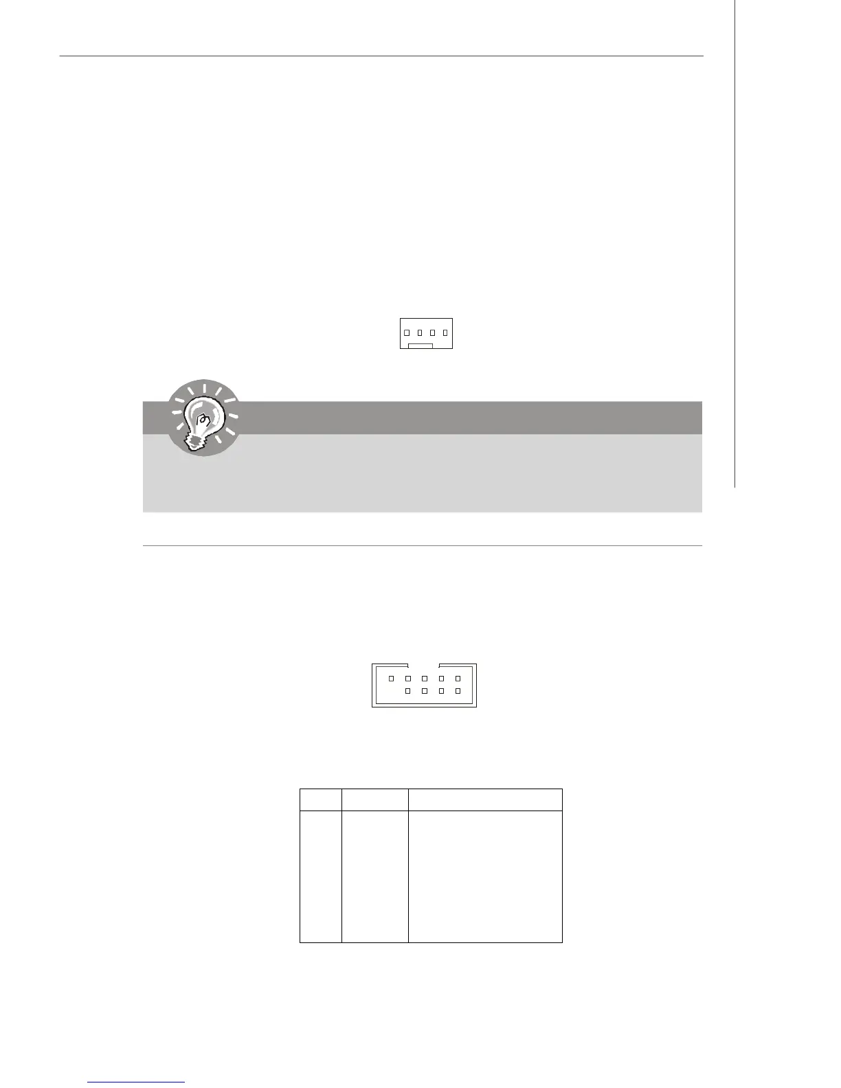
Serial Port Connectors: COM1, COM 2
The mainboard provides 9-pin headers as RS232/422/485 COM ports to connect
serial devices.
PIN SIGNAL DESCRIPTION
1 DCD Data Carry Detect
2 SIN Serial In or Receive Data
3 SOUT Serial Out or Transmit Data
4 DTR Data Terminal Ready
5 GND Ground
6 DSR Data Set Ready
7 RTS Request To Send
8 CTS Clear To Send
9 RI Ring Indicate
Pin Definition
CPU_FAN1
S
E
N
S
O
R
+
1
2
V
G
N
D
C
O
N
T
R
O
L
COM1/2
19
2
10
 Loading...