2-12
MS-9643 Mainboard
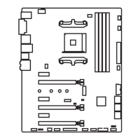
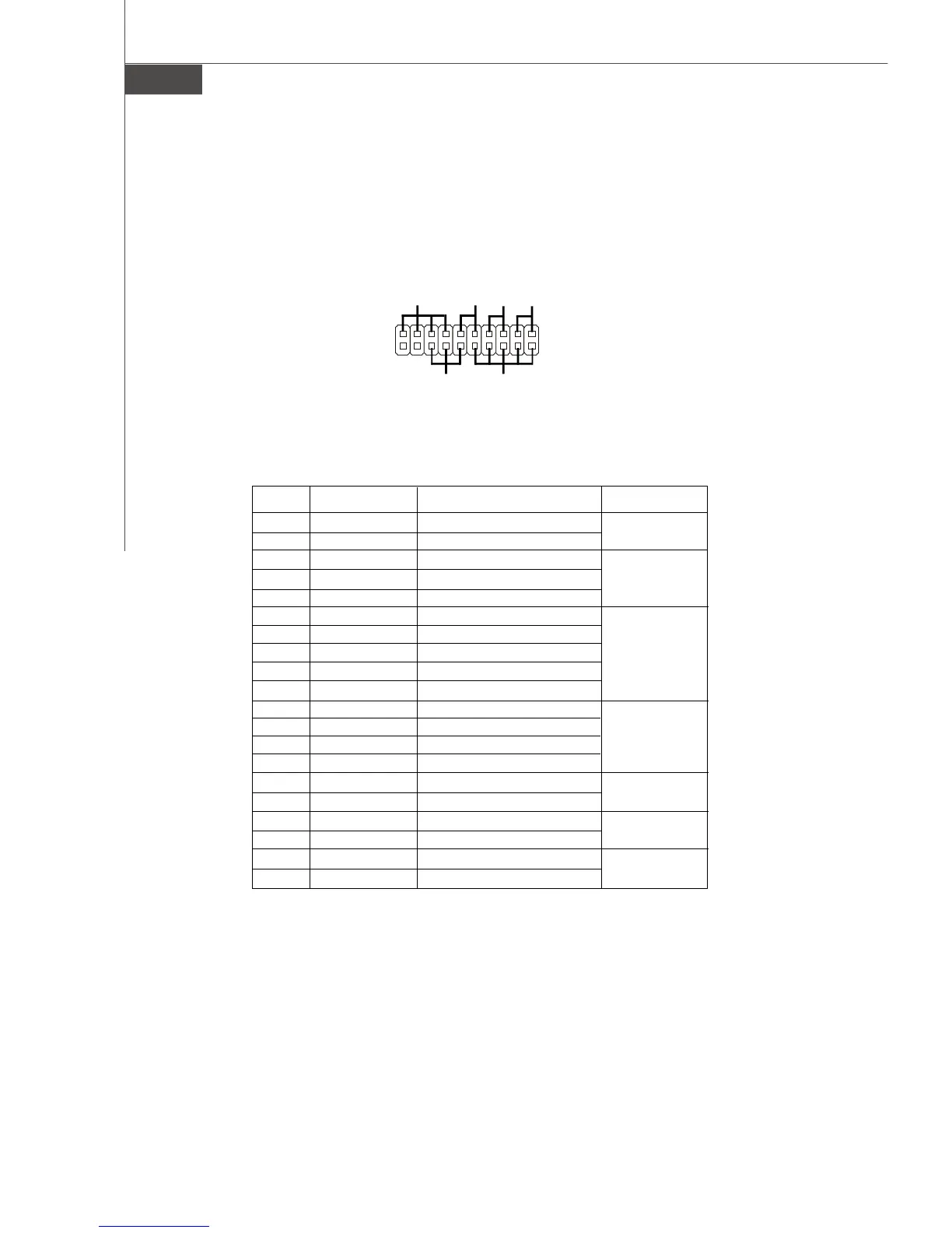
Front Panel Connector: JFP1
The mainboard provides one front panel connector for electrical connection to the
front panel switches and LEDs.
1
2 20
JFP1
19
Power
LED
ATX
Power
Chassis
Speaker
Reset
Button
HDD
LED
Power On
Button
PIN SIGNAL FUNCTION PIN GROUP
1 +5V Power
3 NC No Connection
5 PLED Power LED Signal
7 NC No Connection
9 GND Ground
11 GND Ground
13 NC No Connection
15 PWRON Power-On Signal
17 +5VSB Standby Power
19 NC No Connection
2 WDSPK Speaker Signal
4 NC No Connection
6 NC No Connection
8 +5V Power
10 RESETBT Reset Button Signal
12 GND Ground
14 HDDLED Hard Disk LED Signal
16 +5V Power
18 +5VSB Standby Power
20 PWRBT Power Button Signal
JFP1 Pin Definition
Power LED
ATX Power
Chassis Speaker
Reset Button
Hard Disk LED
Power On Button
 Loading...