EasyManua.ls Logo

MSI Z170-A PRO User Manual

MSI Z170-A PRO
150 pages
To Next Page IconTo Next Page
To Previous Page IconTo Previous Page
Page #134 background imageLoading...
Page #134 background image
22
Компоненты материнской платы
JCI1: Разъем датчика открытия корпуса
К этому разъему подключается кабель от датчика открытия корпуса.
Нормально
(По умолчанию)
Разрешить запись
по событию
открытия корпуса
Использование датчика открытия корпуса
1. Подключите подключите датчик открытия корпуса к разъему JCI1.
2. Закройте крышку корпуса.
3. Войдите в BIOS > Settings > Security > Chassis Intrusion Configuration.
4. Установите Chassis Intrusion на Enabled.
5. Нажмите клавишу F10, чтобы сохранить настройки и выйти, а затем нажмите
клавишу Enter, чтобы выбрать Yes.
6. При открытии корпуса на экране будет появлятся предупреждающее
сообщение каждый раз при включении компьютера.
Сброс сообщения об открытии корпуса
1. Войдите в BIOS > Settings > Security > Chassis Intrusion Configuration.
2. Выберите Chassis Intrusion, Reset.
3. Нажмите клавишу F10, чтобы сохранить изменения и выйти, а затем
нажмите клавишу Enter, чтобы выбрать Yes.
EZ Debug LED: Индикатор отладки
Индикатор сигнализирует о неисправностях на материнской плате.
CPU - указывает, что процессор не обнаружен
или поврежден.
DRAM - указывает, что память DRAM не
обнаружена или повреждена.
VGA - указывает, что видеокарта не обнаружена
или повреждена.

Table of Contents

Question and Answer IconNeed help?

Do you have a question about the MSI Z170-A PRO and is the answer not in the manual?

MSI Z170-A PRO Specifications

General IconGeneral
SocketLGA 1151
ChipsetIntel Z170
Form FactorATX
Memory TypeDDR4
Memory Slots4
Maximum Memory Supported64 GB
SATA 6Gb/s6
M.2 Slots1
USB 3.0 Ports6
USB 2.0 Ports6
USB 3.1 Gen1 (Rear)2
USB 3.1 Gen2 (Rear)1
USB 2.0 (Rear)2
USB 3.1 Ports (Rear)1
USB 3.1 Ports (Front)1
PCIe x16 Slots2
PCIe x1 Slots3
AudioRealtek ALC892
LAN1 x Gigabit LAN

Summary

Installing a Processor

Installing DDR4 Memory

Connecting the Front Panel Header

Installing the Motherboard

Installing SATA Drives

Installing a Graphics Card

Connecting Peripheral Devices

Connecting the Power Connectors

Power On

Safety Information

Specifications

Rear I/O Panel

LAN Port LED Status Table

Table detailing LAN port LED status and speed.

Audio Ports Configuration

Diagram showing audio port connections and channel assignments.

Overview of Components

CPU Socket

Details on the CPU socket, installation, and important notes.

DIMM Slots

Information on memory module installation and slot recommendations.

PCI_E1~6: PCIe Expansion Slots

Explains PCIe slot types, configurations, and installation guidelines.

SATA1~6: SATA 6Gb/s Connectors

Describes SATA connectors and their interface.

SE1_21-SE2_65: SATAe Connectors

Describes SATA Express connectors and their usage.

M2_1: M.2 Slot

Details on the M.2 slot, installation, and compatibility.

JFP1, JFP2: Front Panel Connectors

Pinout and connection details for front panel connectors.

JPWR1~2: Power Connectors

Explains ATX power connector pinouts and requirements.

JUSB1~2: USB 2.0 Connectors

Details on USB 2.0 front panel connector pinouts.

JUSB3~4: USB 3.1 Gen1 Connectors

Details on USB 3.1 Gen1 front panel connector pinouts.

Charger Port

Information about the USB charger port for fast charging.

JAUD1: Front Audio Connector

Pinout and connection details for the front audio connector.

CPUFAN1~2, SYSFAN1~3: Fan Connectors

Explains PWM and Voltage Mode fan connectors and their usage.

Controlling the fan speed

Describes methods to manage fan speed via BIOS or software.

JLPT1: Parallel Port Connector

Pinout for the optional parallel port connector.

JCOM1: Serial Port Connector

Pinout for the optional serial port connector.

JTPM1: TPM Module Connector

Details for the TPM module connector.

JBAT1: Clear CMOS (Reset BIOS) Jumper

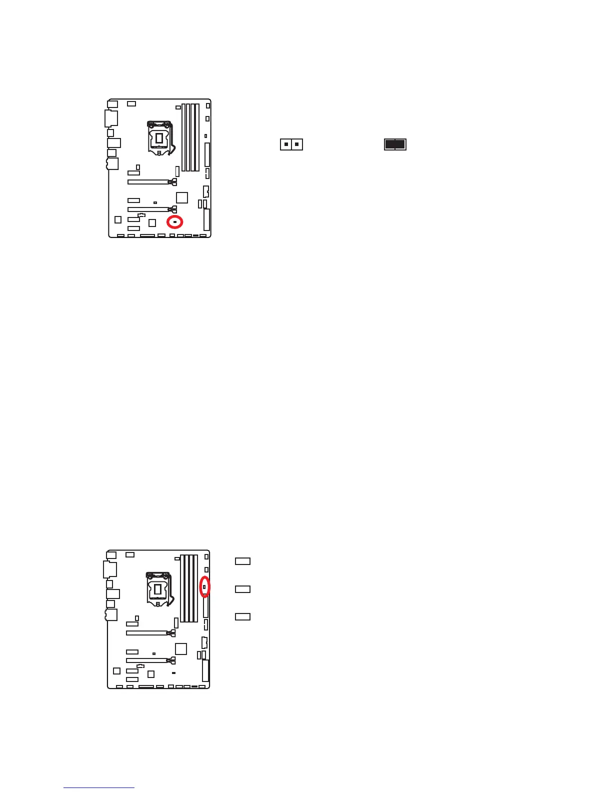
Instructions for clearing CMOS and resetting BIOS using a jumper.

JCI1: Chassis Intrusion Connector

Pinout for the chassis intrusion detection connector.

EZ Debug LED: Debug LED indicators

Explains the status indicated by the EZ Debug LEDs.

BIOS Setup

Entering BIOS Setup

Methods to access the BIOS setup utility during boot.

Resetting BIOS

Procedures for restoring default BIOS settings to solve issues.

Updating BIOS

Guides on updating the motherboard BIOS using M-FLASH or Live Update.

EZ Mode

Overview of the basic BIOS interface for simple settings.

Advanced Mode

Overview of the advanced BIOS interface for detailed configurations.

OC

Settings related to CPU overclocking, frequency, and voltage adjustments.

Software Description

Installing Windows® 7/ 8.1/ 10

Step-by-step guide for installing Windows operating systems.

Installing Drivers

Instructions for installing essential motherboard drivers.

Installing Utilities

Guide for installing optional MSI utilities for enhanced functionality.

Regulatory Notices

FCC Compliance Statement

Statement regarding compliance with FCC rules for digital devices.

Battery Information

Guidelines for battery disposal and recycling.

Chemical Substances Information

Information on chemical substances compliance with regulations.

Technical Support

Related product manuals