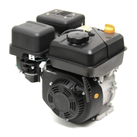
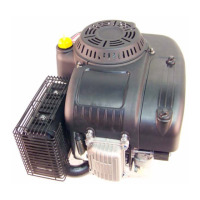
T65 Series Vertical Shaft Engines
74
Engine brake and stop switch (if equipped)
The stop switch and brake (for lawn mower applications) must be able to stop the blade from rotating within 3.0 sec-
onds after the release of the safety bail, per ANSI B71.1-2003 standard.
NOTE: The brake should be replaced when the thickness of the pad is less than 0.25” (6.35 mm) at the thin-
nest spot.
To replace the brake assembly:
1. Unplug the spark plug.
2. Drain the fuel out of the fuel tank into an approved
container.
3. Disconnect the fuel line from the tank.
4. Remove the recoil assembly by following the steps
described in Chapter 6: Starter.
5. Lift the blower housing off of the engine.
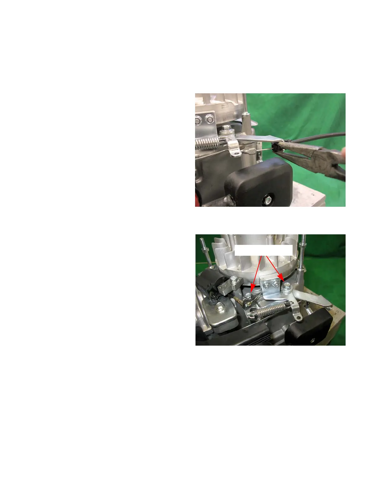
6. Remove the engine control cable by:
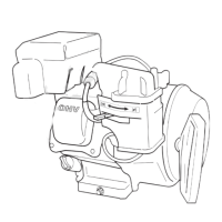
6a. Unhook the Z-fitting from the brake assembly.
6b. Squeeze the barbs together at the engine end
of the cable housing and push it through the
brake assembly. See Figure 7.16.
7. Disconnect the connector in the lead that goes to
the module.
8. Remove the two bolts securing the brake assembly.
See Figure 7.17.
9. Install the brake assembly by following the previous
steps in reverse order.
10. Test run the engine in a safe area before returning it
to service.
Figure 7.16
Releasing the engine control
cable from the bracket
Figure 7.17
Remove these bolts
 Loading...