5 N b + I2 (P + N - 5 G)
5 (I1 + I2) - I2
M >
10
Subject to modications
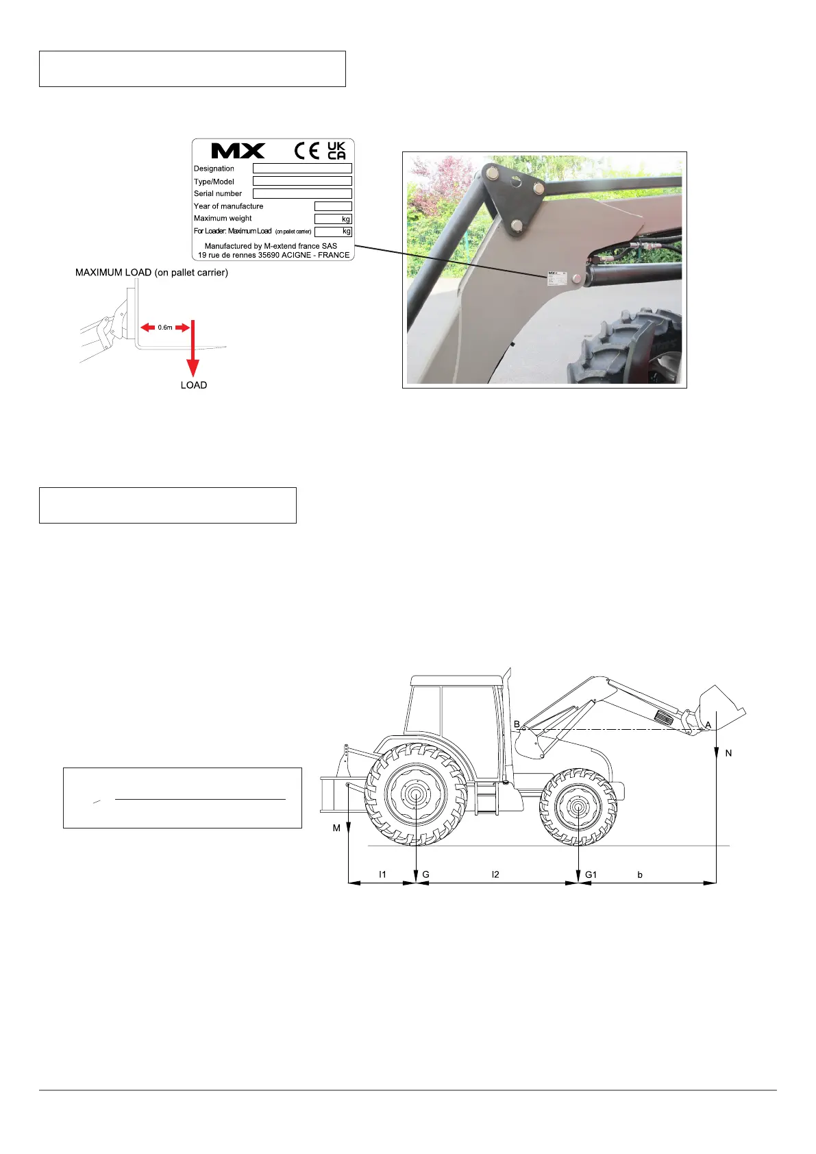
3. IDENTIFICATION PLATE
The identication plate is located inside the loader’s right arm.
The serial number and loader model shown on this plate must be quoted in any request for spare parts information
or technical assistance.
4. COUNTERWEIGHT
The stability of the tractor-loader unit can only be ensured with a counterweight installed on the rear of the tractor.
This should ensure that 20% of the gross weight (tractor, loader, implement, maximum load and counterweight) bears on
the rear axle of the tractor for optimum working safety.
The formula below is used to calculate the counterweight (M) (standard EN12525 + A2 2010).
G: Load on the rear axle, with no counterweight, with empty implement (kg).
G1: Load on the front axle, with no counterweight, with empty implement (kg).
b: Distance from front axle to the implement’s centre of gravity (mm).
I1: Distance from the linkage arm pin to the rear axle (mm).
I2: Wheelbase (mm).
N: Usable load of the loader for implement pivot point (A) horizontal with the loader pivot point (B) (kg).
P: G + G1 (kg).
M: Counterweight (kg).
 Loading...