Chapter 5 Maintenance and Inspection
UD-series Screw Compressor 5.5 Reassembly
5-45
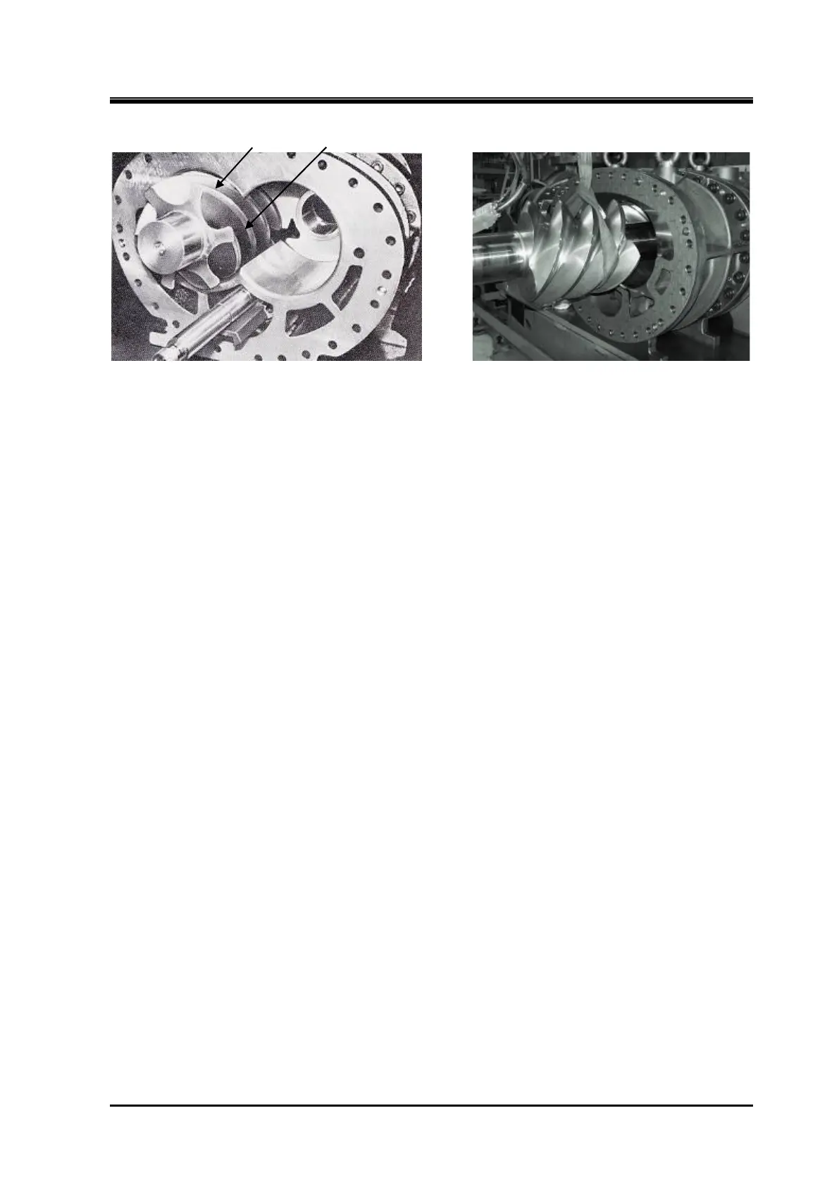
① ②
Install the F Rotor(200S) Install the M Rotor (400M)
b)Of the robes of the F rotor, check the position of the groove between the robes of the robe tip
marks ① and ②.
c)Combine the teeth of the M rotor robe tip mark ① with the groove between the robes of the F
rotor robe tip mark ① and ②.
While rotating the M rotor, install it to the middle of the rotor
casing, remove the hanging belt, and push it in.
NOTE) Be sure to observe these combinations, as changing the robe combination may change
the position of the robe contact or the clearance between the robes and may cause the
vibration and the noise during operation.
d)After assembling the rotor to the casing, apply oil to the robe surface
e)Do not turn the rotor as the outer circumference of the rotor touches the casing.
Turning it can
damage the edges of the robes.
5.5.4 Suction Cover, Side Bearing and Oil Injection Pipe
a) Install the side bearings in the suction cover in the same way as the main bearings are
installed in the bearing head.
Be careful not to forget to assemble the "O" ring (part number
433) of the outside diameter of the side bearing.
The fitting between the bearing and the
bearing hole of the suction cover is a clearance fit as in the case of the main bearing.
If the fit is
strong, be sure to hit it with a pad instead of hitting the bearing directly.
In addition, to ensure
that the positioning spring pin (part number 8) and the cut out of the side bearing are aligned
when assembled, attaching the guide rod to the pin makes the work easier.
The side bearing
has a clearance fit in the suction cover hole.
Always ensure that the spring pins (part number 8)
of the side bearings fit into the cutouts in the bearings.
* The arrow above indicates that if the guide rod position shifts during pushing, re-install it.
 Loading...
