Chapter 5 Maintenance and Inspection
UD-series Screw Compressor 5.4 Disassembly and Inspection
5-23
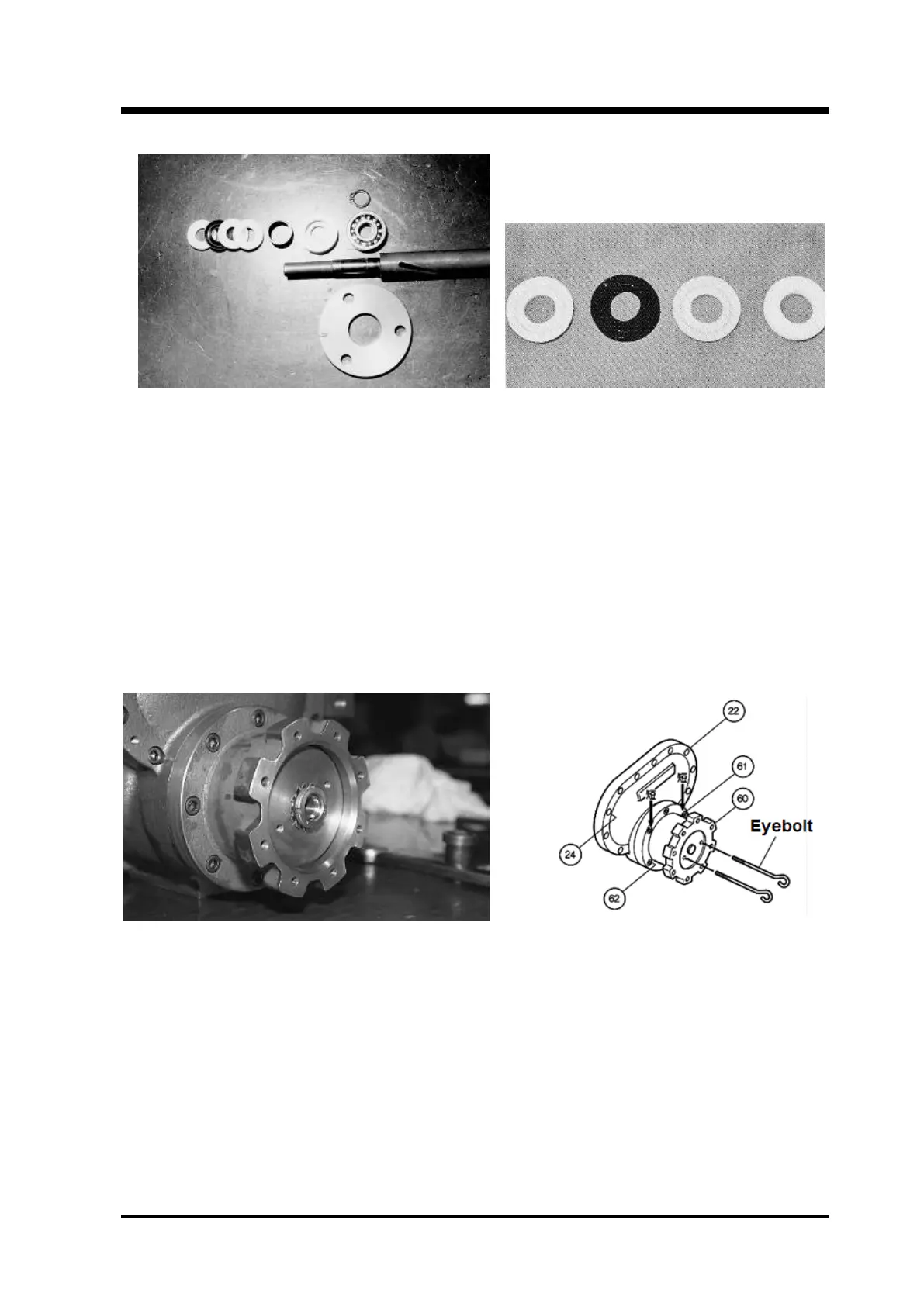
Shaft seal parts of indicator cam Teflon V ring
5.4.5 Unloader Piston and Unloader Cylinder
Disassembly
a) Screw the eyebolts of the disassembly tool into the two screw holes on the unloader piston,
and move the unloader piston to the unloader indicator side to the full load (100 % load)
position.
Bend back the claw lock washer for locking the lock nut that secures the unloader
piston to the push rod.
b) Use a lock nut wrench “sold separately” to loosen the lock nut “part number 69”.
c) Use the eyebolt again to pull the unloader piston out of the push rod.
Bend back the claw lock washer for locking Figure 5-10 Remove Unloader Piston
d) The unloader cylinder is assembled to the balance piston cover with two short hexagon socket
head bolts (part number 61) and to the suction cover with six long hexagon socket head bolts (part
number 62).
e) Remove the tightening bolts on the balance piston cover.
Place a container to receive the oil
coming out from inside, and pull the entire cover toward you to separate the unloader cylinder and
balance piston cover from the suction cover.
Inspection
a) Be sure to replace the cap seal (part number 66) and “O” ring (part number 65) that are
installed on the outer circumference of the unloader piston.
b) If the inner surface of the unloader cylinder is scratched, remove it with fine sandpaper (#400
 Loading...
