NAPCO Gemini C-Series Control Panel Programming Instructions--Volume 1
NAPCO Security Group
Programming Instructions, Volume 1 Page 25
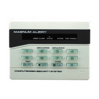
This section will focus on configuring the GEMC-BK1 Burglary keypad. For configuring the GEMC-FK1 Fire keypad,
see the previous page.
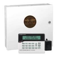
KEYPAD INSTALLATION OVERVIEW
The GEMC-BK1 is a 2-line LCD Burglary access keypad and is the primary operator interface for the Burglary section
of your Gemini C-Series Combination Commercial Fire and Burglary Alarm System. For Fire-Only or Fire/Burglary
combination systems, a GEMC-FK1 is recommended for use as Keypad #1; for Burglary-Only systems, a GEMC-BK1
is recommended for use as Keypad #1. The GEMC-BK1 keypad meets the requirements of UL864 (9th Edition) as the
primary operator interface.
Supports up to fifteen (15) system keypads maximum, with a maximum of seven (7) GEMC-FK1 Fire keypads al-
lowed only in Area 1. The maximum number of Burglary keypads allowed decreases as Fire keypads (or GEM-
ACM modules) are added to the system.
System limit examples:
Burg-Only System: Zero Fire keypads in Area 1, 15 Burglary keypads in Areas 2-8
Combination System: 1 Fire keypad in Area 1, 14 Burglary keypads in Areas 2-8
Combination System: 7 Fire keypads in Area 1, 8 Burglary keypads in Areas 2-8
Fire-Only System: 7 Fire keypads maximum in Area 1 (one Area only in the system)
At least one keypad must be used; only one GEMC-BK1 keypad is required for a single-area Commercial Burglary in-
stallation, and only one GEMC-FK1 keypad is required for a single-area Commercial Fire installation. GEMC-BK1 /
GEMC-FK1 keypads may be intermixed but require different configuration procedures, as described in the following
paragraphs and further in this manual. If there is more than one keypad in the system, only the keypad addressed as
Keypad Number 1 may be used for programming (see Keypad Address, below).
CONFIGURING EACH KEYPAD
Each GEMC-BK1 keypad must be configured for (a) keypad tactile beep; (b) keypad address and (c) Compatibility
number.
To enter the GEMC-BK1 Configuration Mode:
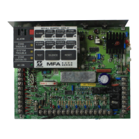
1. Move jumper J1 (located at the upper center of the control panel printed circuit board) from pins 1-2 (top two) to
pins 2-3 (bottom two). NOTE: See the Wiring Diagram.
IMPORTANT: DO NOT touch the J1 jumper for 2 minutes following any download.
2. After about 15 seconds, the keypad display will read "XX OUT OF SYSTEM", where "XX" indicates the current key-
pad address. All keypad are programmed at the factory as address "01".
3. Press
11123R and proceed as follows (repeat the following procedure for all key-
pads in the system).
Keypad Tactile Beep
Upon entering the Keypad Configuration Mode, "KEYPAD BEEP ON" will be
displayed, indicating that the tactile beep, which sounds when any button is
pressed, is on. To turn off the tactile beep, press the
U button (notice the U
button toggles the tactile beep on and off). Press the
R button to contin-
ue or press the C button to exit.
Entry Sounder
To turn off the keypad sounder during the entry delay time, press the U but-
ton (the
U button toggles the entry sounder on and off). Press the R
button to continue or press the
C button to exit.
Keypad Address
If more than one keypad is installed, each must be assigned a unique key-
pad address number (that is, no two keypads may be numbered alike):
GEMC-BK1 KEYPAD CONFIGURATION MODE
Keypad Beep
ON
Keypad Address
01
Entry Sounder
ON
 Loading...