© National Instruments Corporation 15 NI 446X Calibration Procedure
10. Average all the values in the array returned from the acquisition. The
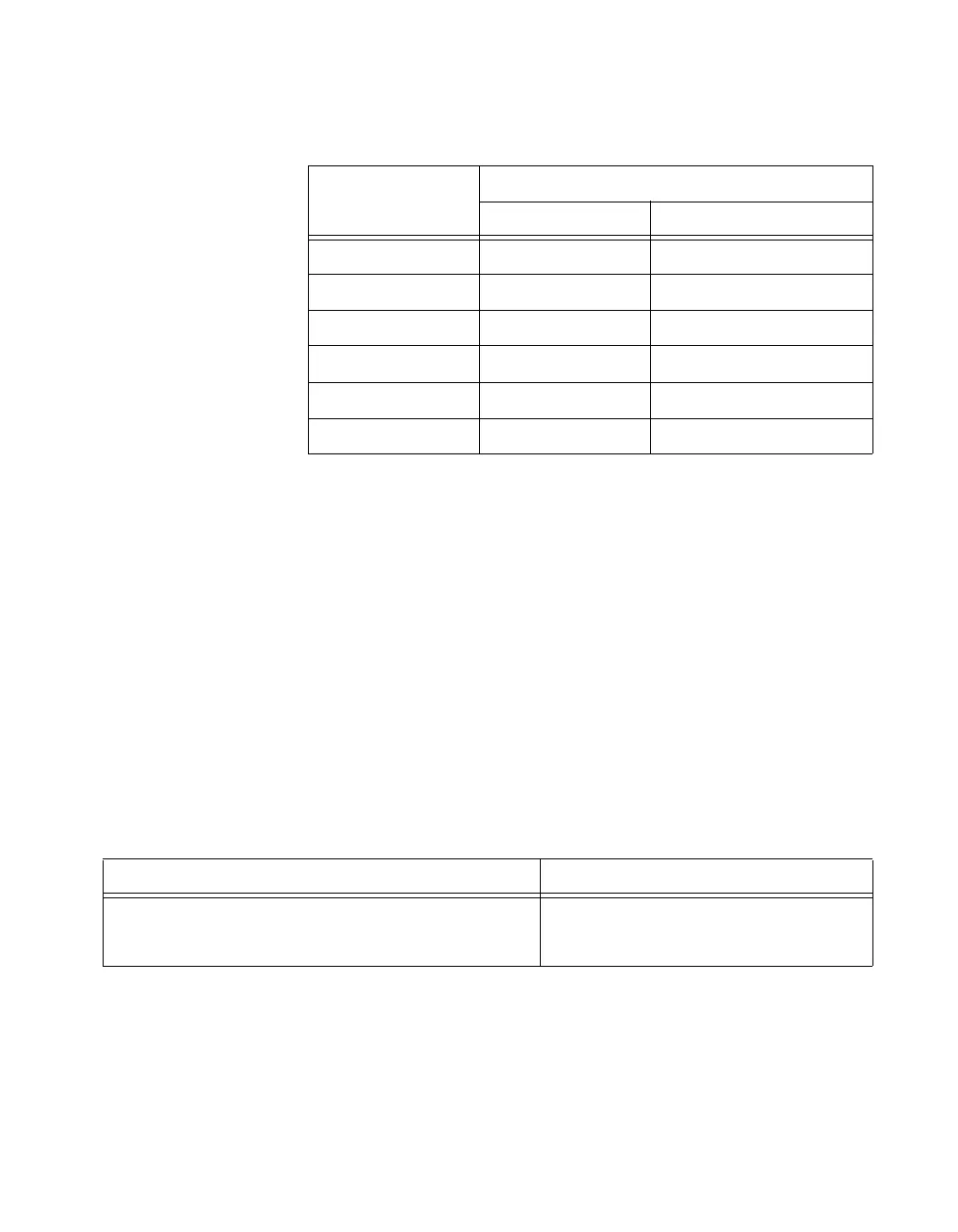
average is the resulting offset for AI 0 at –20 dB device gain setting.
Compare this value to the limits in Table 2.
11. Repeat steps 2 through 10 for each different gain value that is set in
step 4, using the device gain values in Table 2.
12. Repeat steps 1 through 11 for all remaining analog input channels of
the device. Replace
ai0 with the appropriate channel name in function
call parameters
physicalChannel and channel.
Verifying AI Gain Accuracy
Complete the following steps to verify AI gain accuracy:
1. Connect the output of the calibrator to the analog input channel 0 of the
device.
2. Output 9.0 VDC using the calibrator.
3. If you use C function calls, create a task using the following function.
If you use LabVIEW, skip this step. The task is created in step 4 in
LabVIEW.
You use the object
myTaskHandle in all subsequent NI-DAQmx
function calls.
Table 2. AI Offset Limits
Device Gain
Device Input Offset
Min (mV) Max (mV)
–20 –7.0 7.0
–10 –5.0 5.0
0 – 0.7 0.7
10 – 0.5 0.5
20 – 0.2 0.2
30 – 0.1 0.1
NI-DAQmx Function Call LabVIEW Block Diagram
Call DAQmxCreateTask with the following parameter:
taskHandle:
mytaskHandleReturnValue
LabVIEW does not require this step.
 Loading...


