© National Instruments Corporation 3 NI 5761R User Guide and Specifications
AUX I/O Connector
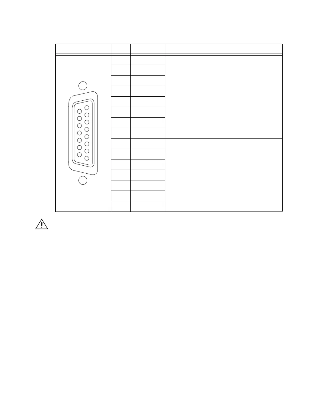
Table 2 shows the pins assignments for the AUX I/O connector on the NI 5761.
Caution Connections that exceed any of the maximum ratings of any connector on the NI 5761R
can damage the device and the chassis. NI is not liable for any damage resulting from such signal
connections. For the maximum input and output ratings for each signal, refer to the Specifications
section of this document.
Table 2. NI 5761 AUX I/O Connector Pin Assignments
Micro-D Connector Pin Signal Signal Description
1 AUXIO0 General-purpose digital input or output channels.
2 AUXIO1
3 AUXIO2
4 AUXIO3
5 AUXIO4
6 AUXIO5
7 AUXIO6
8 AUXIO7
9 GND Ground.
10 GND
11 GND
12 GND
13 GND
14 GND
15 GND
9
10
11
12
13
14
15
1
2
3
4
5
6
7
8
 Loading...