Chapter 3 Register Map and Descriptions
©
National Instruments Corporation 3-9 PCI E Series RLPM
Configuration Memory Low Register
The Configuration Memory Low Register works with the Configuration Memory High
Register to control the input channel selection multiplexers, gain, range, and mode settings.
The values written to these registers are placed into the Configuration Memory, which is
sequenced through during an acquisition. This register contains seven of these bits. The
contents of the Configuration Memory are emptied by a control register in the DAQ-STC.
Address: Base address + 10 (hex)
Type: Write-only
Word Size: 16-bit
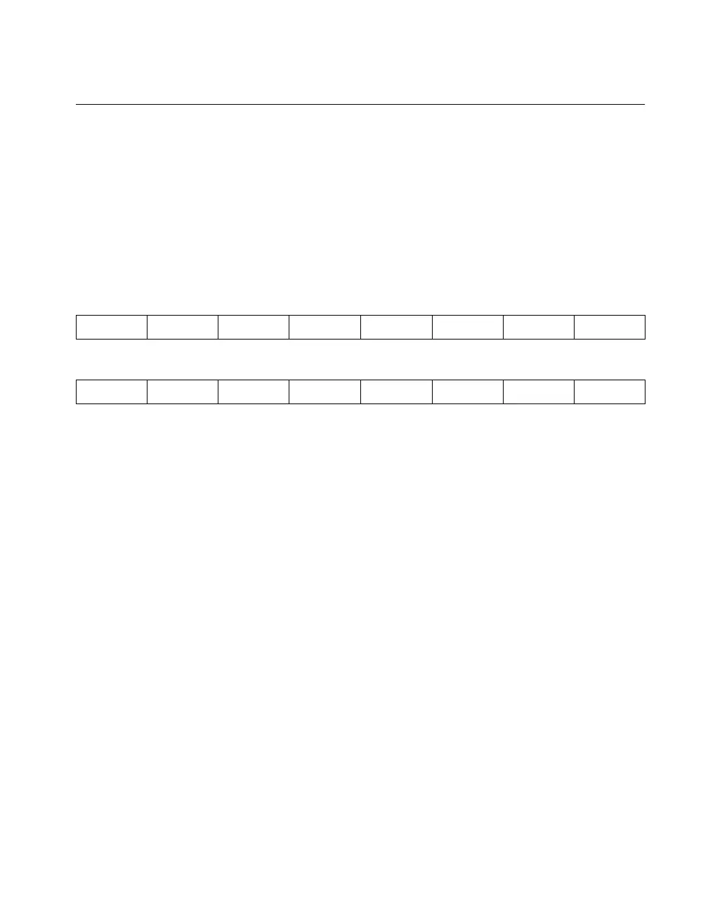
Bit Map:
Bit Name Description
15 LastChan Last Channel—This bit should be set in the last entry of
the scan sequence loaded into the channel configuration
memory. More than one occurrence of the LastChan bit is
possible in the configuration memory list for the
interval-scanning mode. For example, there can be
multiple scan sequences in one memory list.
14–13, Reserved Reserved—Always write 0 to these bits.
11–10,
7–3
12 GenTrig General Trigger—This bit synchronizes actions in the
DAQ-STC with the scan list. When this bit is set, an active
low trigger pulse is sent into the RTSI_BRD0 input of the
DAQ-STC during the CONVERT signal. This trigger is
used at the application level and can perform such actions
as time stamping and starting waveform generation.
9 DitherEn Dither Enable—This bit controls the dither circuitry
feeding the analog input. If this bit is set, approximately
±0.5 LSB of white Gaussian noise is added to the input
signal. This bit is reserved on the PCI-MIO-16XE-50,
15 14 13 12 11 10 9 8
LastChan Reserved Reserved GenTrig Reserved Reserved DitherEn Unip/Bip
7 6 5 4 3 2 1 0
Reserved Reserved Reserved Reserved Reserved Gain2 Gain1 Gain0

 Loading...