20 | ni.com | NI PXI-4130 Calibration Procedure
Refer to the Verifying Voltage Measurement Accuracy section and the Verifying Current
Measurement Accuracy section for instructions on running these measurement accuracy tests.
Voltage Load Regulation
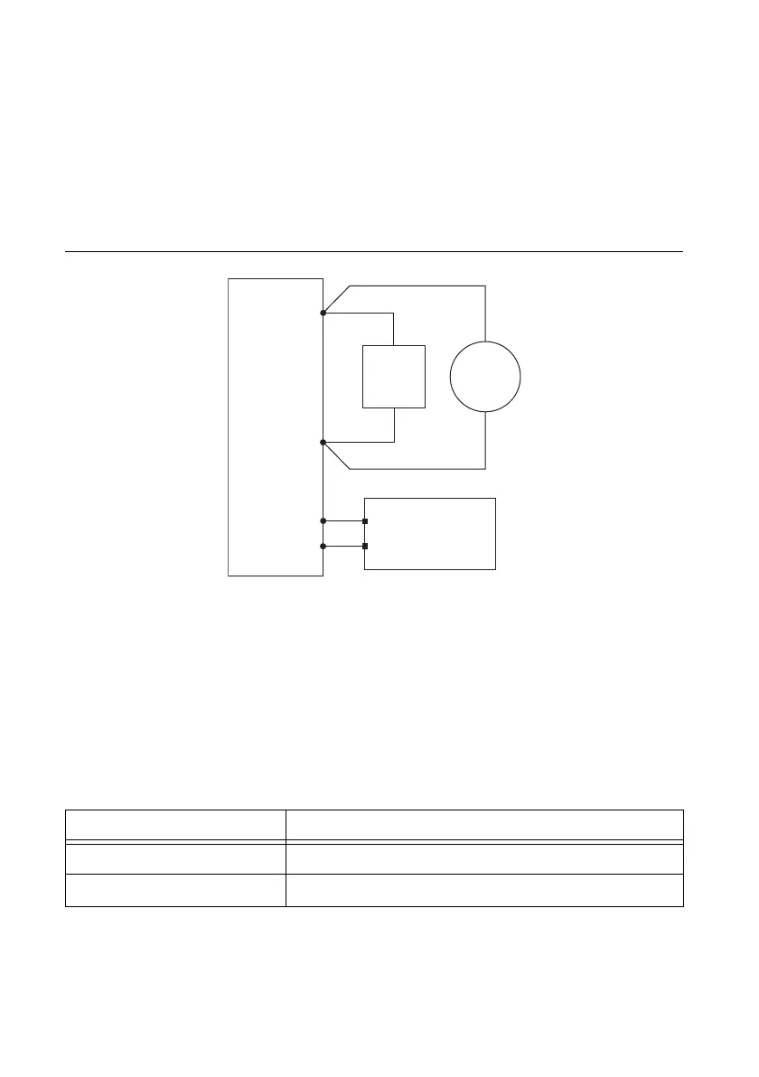
To verify voltage load regulation, use the NI 4130 in Constant Voltage mode and confirm that
the output voltage change falls within calculated limits while varying the load current using an
external load. Table 9 lists the resistance values and measurements needed to complete
verification. Refer to Figure 6 for the necessary output connections.
Figure 6. Voltage Load Regulation Verification Connection Diagram
1. For each test, connect the first specified resistance (R
1
) to the specified channel of the
NI 4130.
2. While taking a current measurement with the NI 4130 (I
1
), use the DMM to measure the
voltage across the output of the NI 4130 (V
1
).
3. Change the load from R
1
to R
2
and repeat the previous step.
4. Record the voltage and current measurements for both resistances.
5. Calculate the Voltage Change Limit using the formulas in Table 9, where the current is in
amps.
Table 9. NI 4130 Voltage Load Regulation Voltage Change Limit Formulas
6. Subtract the two voltage measurements, V
1
- V
2
, to calculate the Voltage Change. The test
passes if the Voltage Change falls within the calculated Voltage Change Limit.
Channel Voltage Change Limit
0 ± (I
1
- I
2
) × 0.0252
1 ± (I
1
- I
2
) × 0.02
NI 4130
Load
+
–
+
–
LO Sense
HI Sense
HI
LO
DMM
Voltage
Mode
NI APS-4100
A
uxiliary Power
Supply
+
–
AUX IN +
AUX IN –

 Loading...


