1-18 | ni.com
Chapter 1 Installation and Preparation
Even if you turn the output off or turn the POWER switch off, if the bleeder on/off
setting (CF11) is set to oFF, the voltage that was present when the output was on will
remain at the output terminals. Set the bleeder on/off setting to on before you touch
the sensing terminals.
Regardless of whether local sensing or remote sensing is used, be sure to attach the
sensing terminal cover before turning the POWER switch on.
If the sensing cables come loose, the output voltage across the load may become unstable, and
an excessive voltage may be applied to the load. If an appropriate OVP trip point is set, the OVP
will trip before an excessive voltage is generated.
When you are finished with remote sensing, return to local sensing mode.
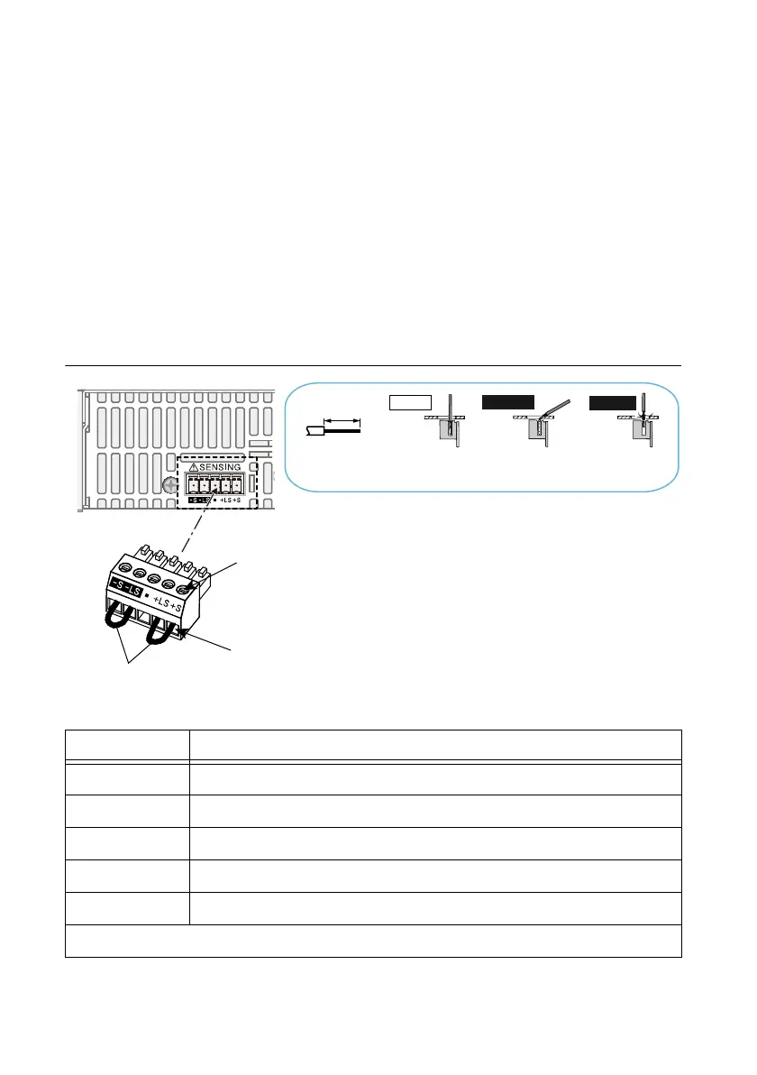
Figure 1-19. Sensing Cable Connections
Table 1-2. Sensing Terminals and Functions
Terminal Function
-S Negative remote sensing terminal.
-LS Negative local sensing terminal connected to the negative output terminal
— Not connected.
+LS Positive local sensing terminal connected to the positive output terminal.
+S Positive remote sensing terminal.
Sensing cable: AWG28 to AWG16
Strip 7 mm (0.28 inches) of the
cable covering, and then insert
the cable here.
Incorrect
Incorrect
Correct
The wire itself is
in contact with
the chassis.
Wire scraps are
in contact with
the chassis.
Strip gauge
7 mm (0.28 inches)
Use this screw to fix the cables
cables in place so that they do
not come loose.
 Loading...