© National Instruments | 1-21
RMX Programmable Power Supplies User Manual
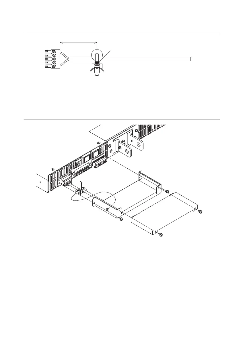
Figure 1-23. Sensing Wire Assembly
7. Firmly attach the sensing connector to the sensing terminals.
8. Fasten the lower side of the connector cover to the panel with the included screws, and then
insert the tip of the band into the hole of the cover. Finally, bring the top and bottom sides
of the connector cover together, and fasten with the included screws.
Figure 1-24. Connector Cover Assembly
9. Turn the power switch on.
40 mm
You can pull out the band that you passed
through the hole by holding this area with
a pair of tweezers.
 Loading...