1-16 | ni.com
Chapter 1 Installation and Preparation
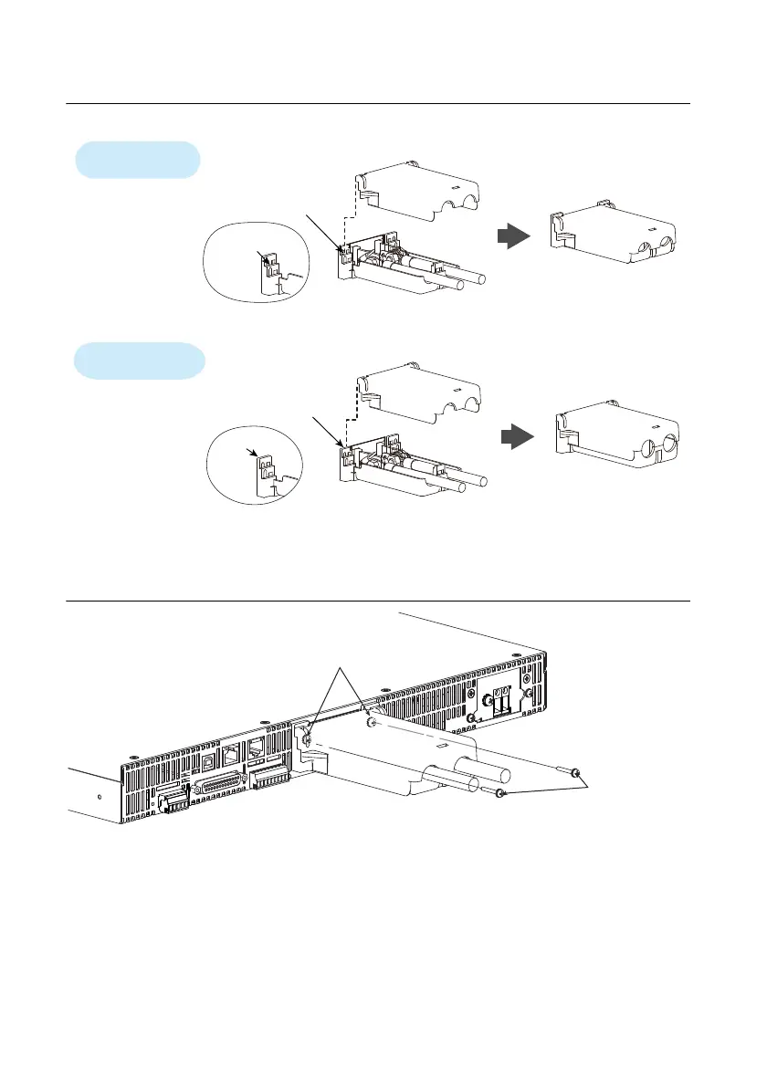
Figure 1-15. Aligning Both Halves of the OUTPUT Terminal Cover
4. Push the OUTPUT terminal cover against the rear panel, and then use the RMX screws to
fix the cover in place. Ensure that the screws are securely fastened.
Figure 1-16. Attaching the OUTPUT Terminal Cover
Top half of the cove
Align the protrusion of
the top half of the cover
with the top section
of the protrusion of the
bottom half.
Bottom half of the cover
For thick load cables
Cover hole diameter:
10 mm to 18 mm
Cover hole diameter:
Up to 10 mm
For thin load cables
Top half of the cover
Align the protrusion of
the top half of the cover
with the middle section
of the protrusion of the
bottom half of the cover.
Bottom half of the cover
Middle
section
Top section
After you have lined up the top and bottom halves
of the cover, use the screws to fix the cover in place.
Screws (M3)
 Loading...