22 | ni.com | NI USB-6001/6002/6003 User Guide
Source/Sink Information
When used in output mode, the default configuration of the digital ports is active drive, allowing
3.3 V operation with a source/sink current limit of ±4 mA.
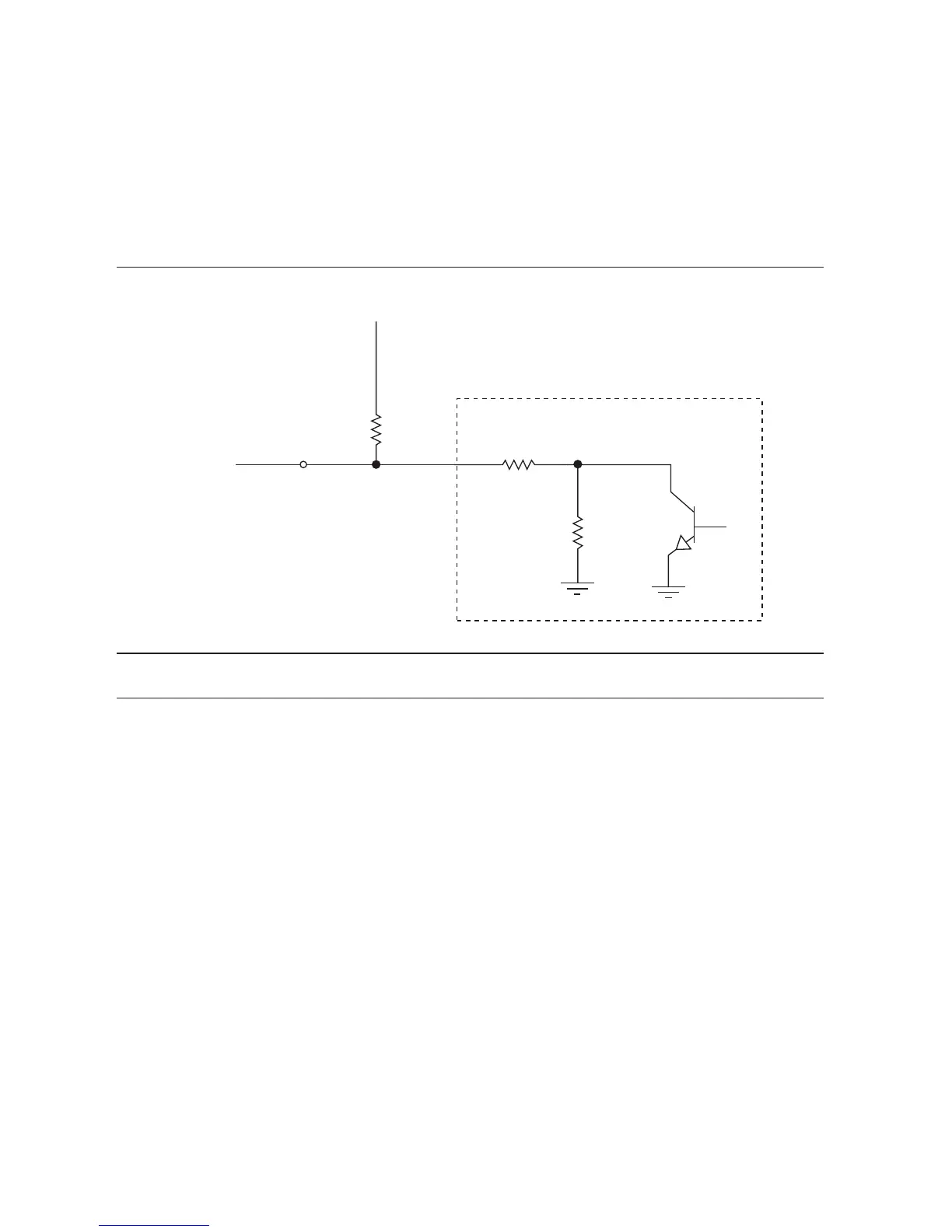
The ports can be configured as open collector using the NI-DAQmx API, allowing operation
with a different voltage level when used in conjunction with an external user-provided pull-up
resistor. Figure 14 shows an example of this connection.
Figure 14. Example of Connecting an External User-Provided Resistor
For more information about configuring NI devices to be open-drain (open collector) or
push-pull (active drive), go to ni.com/info and enter Info Code ex52sp.
I/O Protection
To protect the NI DAQ device against overvoltage, undervoltage, and overcurrent conditions, as
well as ESD events, you should avoid these fault conditions by using the following guidelines:
• If you configure a DIO line as an output, do not connect it to any external signal source,
ground signal, or power supply.
• If you configure a DIO line as an output, understand the current requirements of the load
connected to these signals. Do not exceed the specified current output limits of the
NI DAQ device. National Instruments has several signal conditioning solutions for digital
applications requiring high-current drive.
• If you configure a DIO line as an input, do not drive the line with voltages outside of its
normal operating range. The DIO lines have a smaller operating range than the AI signals.
• Treat the NI DAQ device as you would treat any static-sensitive device. Always properly
ground yourself and the equipment when handling the NI DAQ device or connecting to it.
Note: Ensure that the current flowing across R
pull
does not violate the maximum sinking current specifications
(4 mA).
External
Load
47.5 k
Ω
Onboard
Pull-Down
Resistor
External
Pull-Up
Resistor
DAQ Device
P0.0 with Output Drive Type
Set to Open Collector
V
pull-up
(User Provided, ≤5 V)
R
pull
47 Ω
Protection
Resistor
 Loading...