NI USB-6001/6002/6003 User Guide | © National Instruments | 23
PFI 0 and PFI 1
Using PFI as a Counter Source
You can configure PFI 0 or PFI 1 as a source for counting digital edges. In this mode, either
rising- or falling-edges are counted using a 32-bit counter. For more information, refer to the
device specifications document available at
ni.com/manuals.
Note Edges can only be counted up from either 0 or an initial value such as 1, 2,
3...or 1001, 1002, 1003. Counting down is not supported; you cannot set the initial
count to 100 and count down 99, 98, 97.
Using PFI to Trigger an Analog Input Acquisition
You can configure an analog input task to wait for an edge on PFI 0 or PFI 1 before starting the
acquisition. To do this, configure the AI Start Trigger source to be PFI 0 or PFI 1 and specify
either rising or falling edge.
Using PFI to Trigger an Analog Output Generation
You can configure an analog output task to wait for an edge on PFI 0 or PFI 1 before starting the
acquisition. To do this, configure the AO Start Trigger source to be PFI 0 or PFI 1 and specify
either rising- or falling-edge.
+5 V Power Source
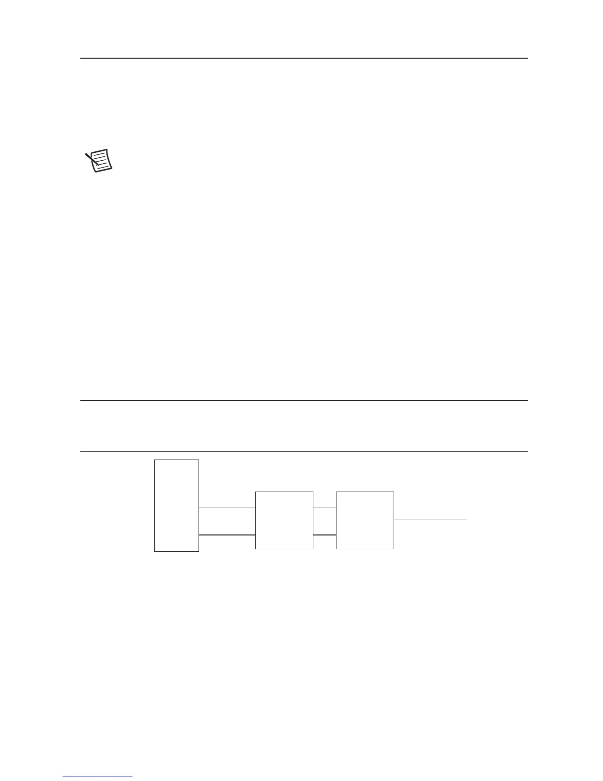
Figure 15 shows the +5 V power source circuitry of the NI USB-6001/6002/6003.
Figure 15. +5 V Power Source Circuitry
The main blocks featured in the +5 V power source circuitry are as follows:
• +5 V Source—Regulated 5 V supply.
• +5 V Protection—Circuit for overvoltage, over current, and short circuit protection.
The +5 V source is limited at 200 mA typically. In case of hard short circuit to ground, this limit
is further reduced to avoid excessive power dissipation.
 Loading...