Page 36/82 PS SERIES HARDWARE SETUP PROCEDURE
Horizontal (PS15R2 only)
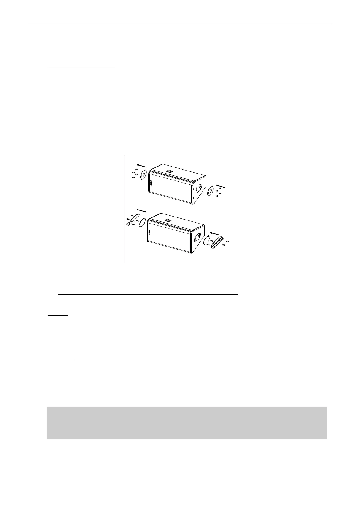
Remove the four TORX screws holding connector plates on both side of PS15R2;
Remove the connector plates from PS15R2;
Fill each screw hole with Locktite 243 or equivalent;
Position external plates from VNI-LBRK kits and secure them using the shoulder screws
supplied with these kits;
Position “L” brackets from VNI-LBRK kits, and secure them to the cabinet using the 4 remaining
shoulder screws supplied with these kits.
Slings and shackles (not provided) are required to secure the cluster under the ceiling;
CABLE SUSPENSION MOUNTING PROCEDURE FOR PS15R2
7.3.4 PS10R2 and PD15R2 wall suspension (vertical or horizontal)
Required item
Vertical
1 VNI-WS10 for PS10R2
1 VNI-WS15 for PS15R2
4 x 12mm diameter screws (not provided)
Horizontal
1 VNI-WS10 and 1 VNI-UBRK10 for PS10R2
1 VNI-WS15 and 1 VNI-UBRK12 for PS15R2
4 x 12mm diameter screws (not provided)
IMPORTANT
Ensure that the wall is strong enough to hold 4 times PS cabinet weight and that the
screws 12mm diameter and corresponding plugs required to fix the VNI-WS on the wall
are properly dimensioned.

 Loading...


