8 ES
GB
Pipe installation
Pipe installation must be carried out in accordance with
current norms and directives.
The water heater is equipped with compression ring
couplings for copper or plastic pipes. Internal support
bushes should be fitted when a plastic pipe or annealed
copper pipe is used. ES 300 is supplied with a reduction
kit from Ø 28 mm to Ø 22 mm, which can be used if
the water heater is installed where a Ø 22 pipe already
exists or is required.
An overflow pipe must be routed from the safety valve
to a suitable drain. The size of the overflow pipe must
be the same as on the safety valve (Ø 22 mm). The over-
flow pipe must be routed downwards to prevent water
pockets and to be frost proof. The outlet of the over-
flow pipe should be visible.
The following equipment should be fitted to the cold
water pipe.
A Shut-off valve
B Non-return valve
47 Safety valve (supplied)
C Vacuum valve
D Mixer valve (if tap water temp exceeds 65 °C)
When the water heater is installed without a mixing
valve, the thermostat setting must be such that the tap
water temperature does not exceed 65 °C. Should a
higher temperature be required, follow applicable direc-
tions for the application.
Installation
Fit the cover discs before the pipe installa-
tion is made.
NOTE!
Pipe installation
LEK
LEK
VPA 450/300 VPA 300/200
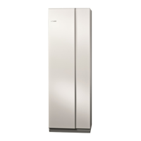
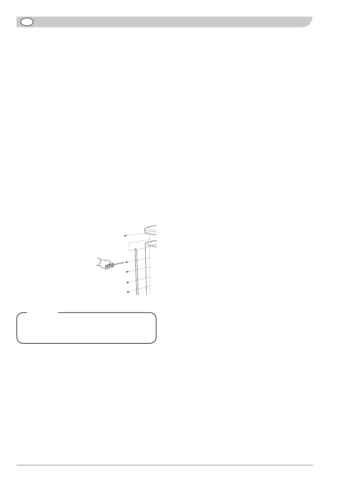
Removing the insulation
(only applies to ES 500)
ES 500 can be made less bulky upon installation by
removing the insulation (water heater diameter without
insulation is Ø 650).
• Remove the electrical cover and electrical panel.
• Loosen all the screws along the joining plate on
both jacket halves.
• Remove the drain valve.
• Lift off the top cover.
• Pull the insulated jacket halves straight off.
Carry out assembly in reverse order. If the screws are
difficult to fit in the old holes, the plate can be turned
upside down, which produces new holes in the insu-
lated jacket halves.
Finally fit all the enclosed cover discs on each connec-
tion by pressing them over the
connections.
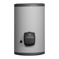
Once the water heater is in
the required position remove
the lifting device from the
top and fit the accompanying
insulation plug in the hole left
by the lifting eye (10).
Assembly
The copper-lined water heater must be assembled up-
right and can be aligned using the adjustable feet (11).
When mounting the unit be sure to leave enough room
for dismounting of the thermostat or immersion heater
in front of the connector house (approx. 400 mm).
 Loading...