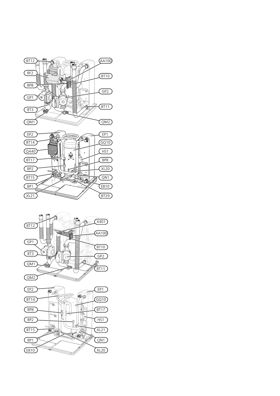
Cooling section
F1355 28 KW, 3 X 400 V
Cooling module EP14
BT11
RF2
BT3
GP1
QM1 QM2
GP2
AA100BT12
BT10
BP8
XL20
EP2
GQ10BT14
BP2
BT17
QN1
HS1
BP1
BT29
EP1
EB10
QA40
BT15
XL21
BP8
Cooling module EP15
BT12
X401
GP2
GP1
BT3
QM1
QM2
BT11
BT10
AA100
EP2
BT14
BP8
BP2
BT15
BP1
EB10
EP1
GQ10
BT17
HS1
XL21
QN1
XL20
PIPE CONNECTIONS
Service connection, high pressureXL20
Service connection, low pressureXL21
HVAC COMPONENTS
Circulation pumpGP1
Brine pumpGP2
Drainage, climate systemQM1
Draining, brine sideQM2
SENSORS ETC.
High pressure pressostatBP1
Low pressure pressostatBP2
Sensor, low pressureBP8
Temperature sensors, heating medium returnBT3
Temperature sensor, brine inBT10
Temperature sensor, brine outBT11
Temperature sensor, condenser supply lineBT12
Temperature sensor, hot gasBT14
Temperature sensor, fluid pipeBT15
Temperature sensor, suction gasBT17
Temperature sensor, compressorBT29
ELECTRICAL COMPONENTS
Joint cardAA100
Compressor heaterEB10
InverterQA40
EMC-filterRF2
Joint connector, compressor and motor moduleX401
COOLING COMPONENTS
EvaporatorEP1
CondenserEP2
CompressorGQ10
Drying filterHS1
Expansion valveQN1
Designations in component locations according to
standard IEC 81346-1 and 81346-2.
13Chapter 3 | The heat pump designNIBE F1355
 Loading...


