SYSTEM DIAGRAM
F1355 consists of two heat pump modules, circulation
pumps and control system with possibility of additional
heat. F1355 is connected to the brine and heating medi-
um circuits.
In the heat pump evaporator, the brine (water mixed
with anti-freeze, glycol or ethanol) releases its energy
to the refrigerant, which is vaporised in order to be
compressed in the compressor. The refrigerant, of which
the temperature has now been raised, is passed to the
condenser where it gives off its energy to the heating
medium circuit and, if necessary, to any docked water
heater. If there is a greater need for heating/hot water
than the compressors can provide it is possible is to
connect an external immersion heater.
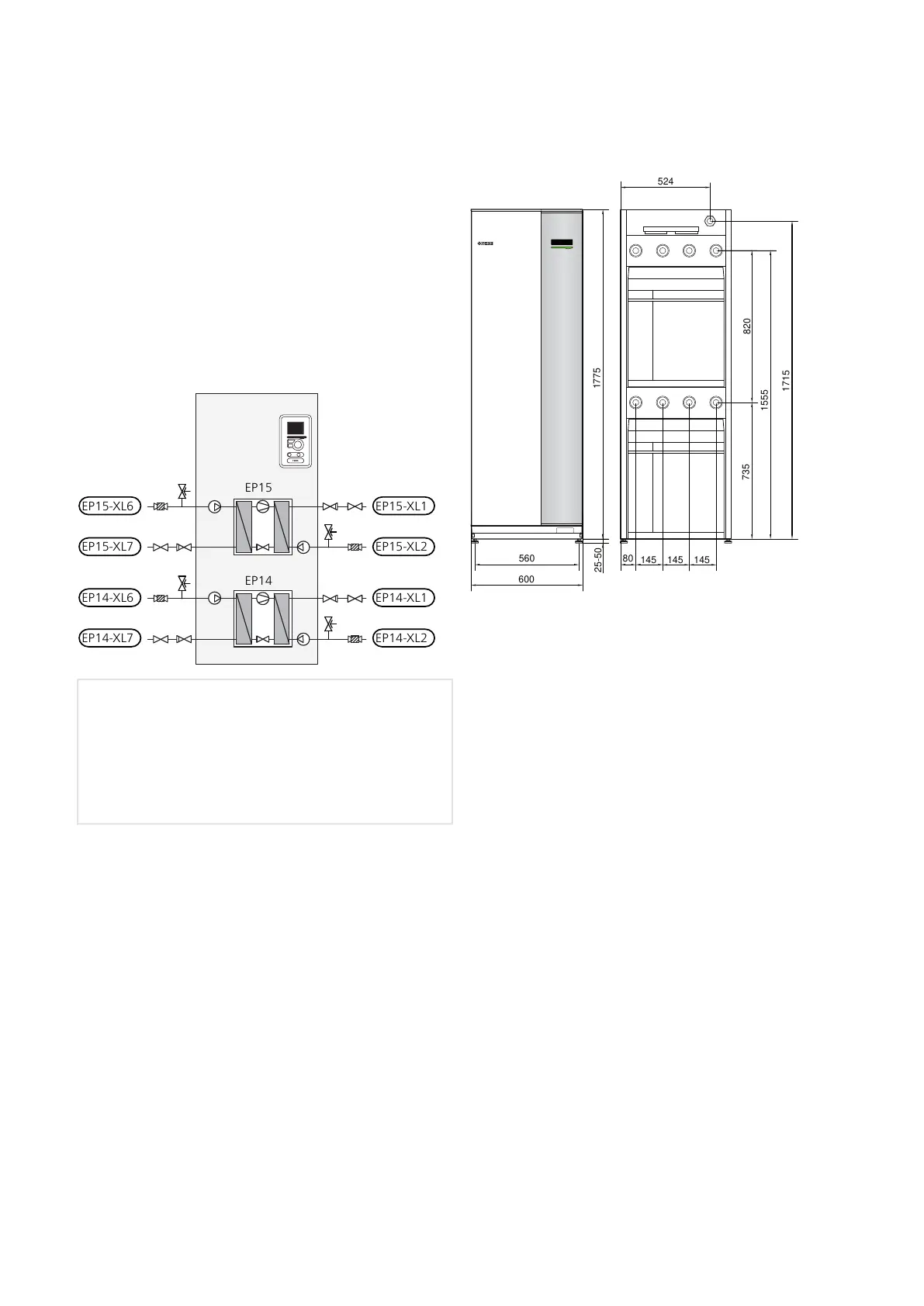
EP15-XL1
EP15-XL2
EP15-XL6
EP15-XL7
EP14-XL1
EP14-XL2
EP14-XL6
EP14-XL7
EP15
EP14
Cooling moduleEP14
Cooling moduleEP15
Connection, heating medium flowXL1
Connection, heating medium returnXL2
Connection, brine inXL6
Connection, brine outXL7
Dimensions and pipe
connections
1775
600
560
440
735
1555
1715
80
145
145
145
450620
820
85
25-50
1775
600
560
440
735
1555
1715
80
145
145
145
524620
820
85
25-50
15Chapter 4 | Pipe connectionsNIBE F1355
 Loading...


