• Wherever the unit is located, walls to sound sensitive
rooms should be fitted with sound insulation.
• Route pipes so they are not fixed to an internal wall
that backs on to a bedroom or living room.
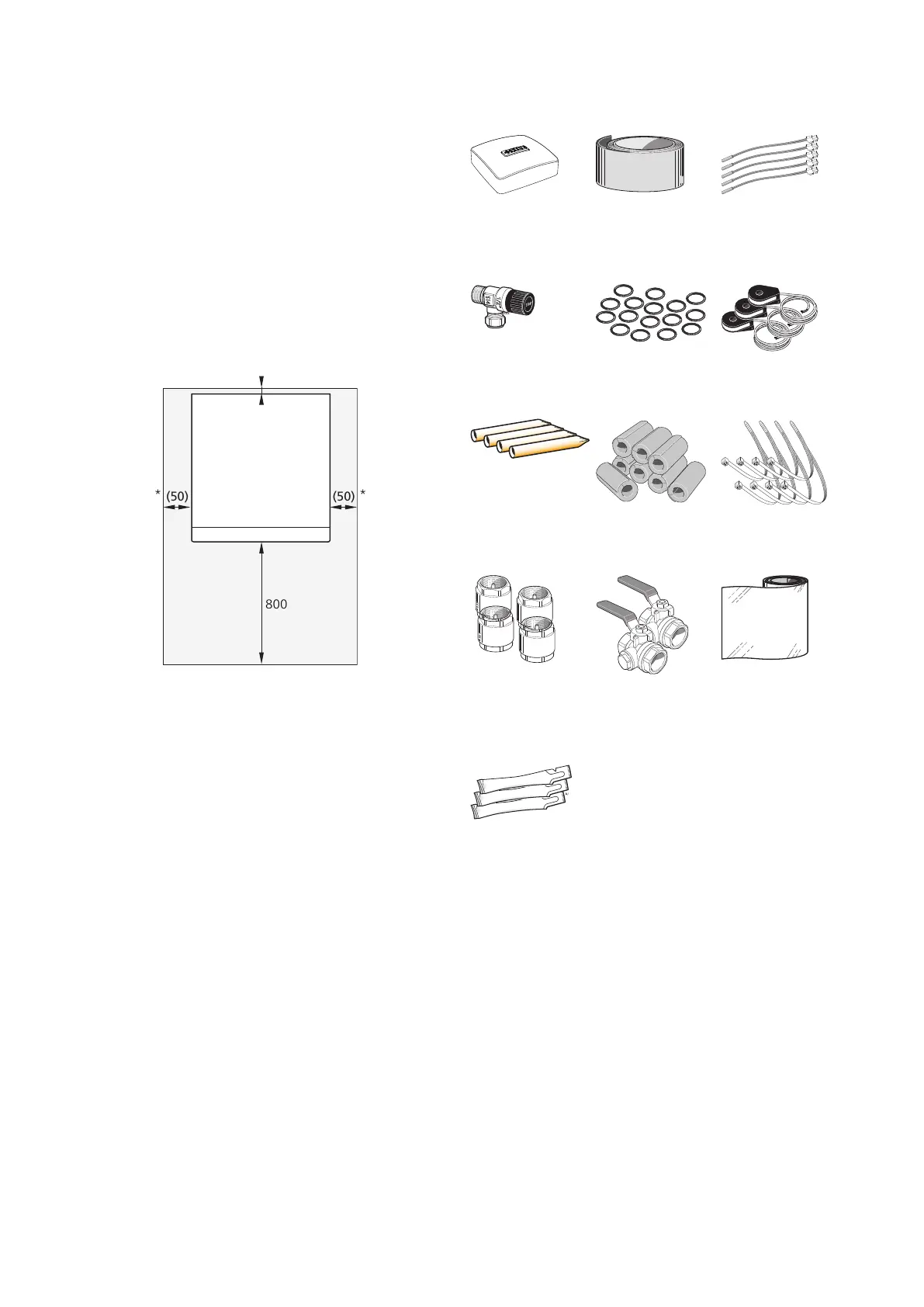
INSTALLATION AREA
Leave a free space of 800 mm in front of the product.
Approx. 50 mm free space is required on each side, to
remove the side panels (see image). The panels do not
need to be removed during service. All service on F1355
can be carried out from the front. Leave space between
the heat pump and the wall behind (and any routing of
supply cables and pipes) to reduce the risk of any vibra-
tion being propagated.
* A normal installation needs 300 – 400 mm (any side) for connection
equipment, i.e. level vessel, valves and electrical equipment.
Supplied components
Temperature
sensor
5 x
Insulation tape
1 x
Outdoor temperat-
ure sensor
1 x
Current sensor
O-rings
16 x
Safety valve
0.3 MPa (3 bar)
1 x
Cable tie
8 x
Pipe insulation
8 pcs
Tubes for sensors
4 x
Aluminium tape
1 x
Filterball
4 x G1 1/4 (intern-
al thread)
Non-return valves
4 x G2, internal
thread
Heat conducting
paste
3 x
LOCATION
The enclosed kit is placed in the packaging next to the
heat pump.
9Chapter 2 | Delivery and handlingNIBE F1355
 Loading...


