English – 5
EN
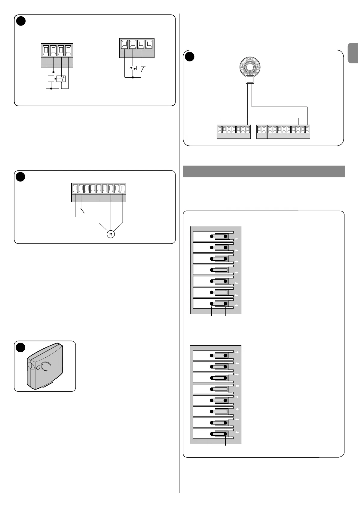
Connection of reection
light beam
+ - Photo
X5
J30 J31
Power supply
24V DC
Safety
light beam
Contact
(opener)
A
B
Connection transmitter
and receiver light beam
+ - Photo
X5
J30 J31
S
E
S=Transmitter
E=Receiver
12
Hooking up direct safety switches
Safety devices which act directly on the control process must be hooked up
to terminal J10 on block X2. These include emergency stop switches, stop
controls, dragging protection and the pedestrian door safety switch.
Hooking up the pedestrian door safety switch
For industrial gates with pedestrian door sections, the safety switch must be
connected to terminal J10 on terminal block X2.
Caution! If pre-assembled, remove the jumpers on J10.
Cable tensioner switch /
Drop protection spring
failure safety device
13
Hooking up control devices such as pull-cord switches
Control equipment can be connected to the D-PRO Automatic control unit
on terminal block X4. The function of these inputs for control equipment is
described in the list of parameters in par. 100 to 103.
Hooking up a radio control unit (radio module)
The 10 pin slot (OXI receiver) is used for inserting Nice OXI or OXIFM OPERA
series receivers.
When doing so, the side with the led/programming button must be facing the
interior of the housing.
If using an OXI radio control unit, make sure to make the appropriate settings!
See the parameters list - P 106
Also refer to the receiver and radio control unit's user instructions.
14
Bridges and jumpers required for the control unit to operate when
components are not connected
Bridges:
Terminal X2 - position J10
Terminal X4 - position J15
Terminal X5 - position J31
Terminal X6 - position J33
Jumpers:
X8-Pin 5-6
X9-Pin 1-2
If a drive with electronic limit switches is hooked up, further bridges will be
required in positions J26, J27 of terminal X7.
All these bridges and jumpers are installed in the factory.
Hooking up the 230V indicator lamp - Models ML and MLT
The ML and MLT indicator lamps can be connected to one of the freely
programmable relay contacts.
If so, they must be connected to a bridge between X1(L1) and X3 (7).
The power terminals are then connected to X1 N and X3 - 9
ML/ML T
123
456897
N BrakeL1 L2 L3
15
CAUTION: If using the ML and MLT indicator lamps, the N wire (230V) must
also be connected to terminal X1 for power.
ADJUSTING THE MECHANICAL LIMIT SWITCHES
Caution! The limit switch adjustments must be done in hold-to-run mode!
To this end, you must set parameter 105 to 6 for the duration of the adjustment.
You can access the limit switch board by unscrewing the housing of the limit
switch itself.
7 white additional limit switch 2 CLOSE
6 green additional limit switch 2 OPEN
5 white additional limit switch 1 CLOSE
4 red safety limit switch CLOSE
3 white limit switch CLOSE
2 red safety limit switch OPEN
1 green limit switch OPEN
8 white additional limit switch 2 CLOSE
7 green additional limit switch 2 OPEN
6 white additional limit switch 1 CLOSE
5 green additional limit switch 1 OPEN
4 red safety limit switch CLOSE
3 white limit switch CLOSE
2 red safety limit switch OPEN
1 green limit switch OPEN
P2 P2 P1 SE E SE E
B A
P2P2P1P1SESE
EE
B A
Adjusting the mechanical limit switches for large size drives with
7 switching cams
Adjusting the mechanical limit switches for small size drives with
8 switching cams
During the adjustment process, the drive is operated in hold-to-run mode with
the OPEN and CLOSE buttons on the housing's cover
When you press OPEN the door should open; if this does not occur set
parameter 75 to 2.

 Loading...