6 – English
EN
If the drive has been installed rotated by 180° (upside down), the door must
nonetheless open when OPEN is pressed; if it does not, set parameter 75 to 2.
The two emergency limit switches must be corrected so that they trip after the
operating limit switches.
Command Wire Motor
X2 - J11/U 1 U
X2 - J11/V 2 V
X2 - J11/W 3 W
X2 - J10 Bridge -
X7 - MiniFit Grey AMP 3 connector
X7 - MiniFit Green AMP 4 connector
X7 - MiniFit White AMP 2 connector
X7 - MiniFit Pink AMP 5 connector
X7 - MiniFit Yellow AMP 6 connector
X7 - MiniFit Brown AMP 1 connector
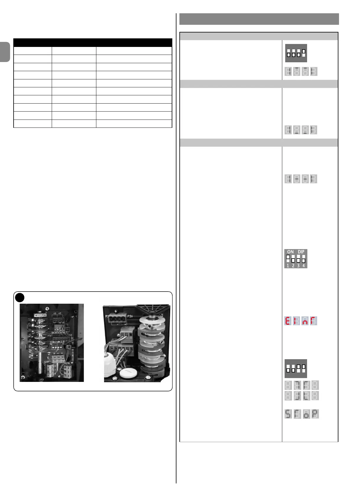
Bottom deactivation position
To adjust the bottom deactivation position limit switch, proceed as follows:
Move the door to the desired CLOSED position.
Set the switching cam 3 E↓(white) to trip the limit switch.
Tighten down mounting bolt A.
The adjustment is made with bolt B.
Move the door to the desired OPEN position.
Set the switching cam 1 E↓(green) to trip the limit switch.
Tighten down mounting bolt A.
The adjustment is made with bolt B.
Safety limit switches 2 SE↓ and 4 SE↑ (red) must be set to trip immediately after
the control limit switch.
Safety limit switches 2 SE↓ and 4 SE↑ (red) are factory set, close to the
operating limit switch.
After the operating test, check the seat of the mounting bolt.
Additional limit switches 8 P2↓ and 7 P2↑ are voltage free closing contacts,
while additional limit switches 6 P1↓ and 5 P1↑ are voltage free switching
contacts.
• In automatic operation, limit switch 6 is used as a pre-limit switch. It
must be adjusted to trip at 5 cm off the ground.
• In hold-to-run mode, it need not be adjusted and be used as a voltage
free contact.
Mechanical limit switches
small type large type
16
The subsequent paragraphs highlight the main programming functions of the
D-PRO Automatic control unit accessible through the dip-switches.
For further details on the available functions, please consult the 'D-PRO
Automatic parameters and error list' addendum accompanying this manual.
ADJUSTING THE DIGITAL LIMIT SWITCHES
Adjusting the end positions
To this end, set dipswitch 4 to “ON”.
ON
SAB
The upper sections of the display will ash.
Adjusting the top end position
Use the OPEN and CLOSE buttons on the
cover of the control unit's housing in hold-to-
run mode to move the door to the top end
position. Save this position by briey pressing
the OPEN or CLOSE programming button on
the front board.
The lower sections will now ash.
Adjusting the bottom end position
Use the OPEN and CLOSE buttons on the
cover of the control unit's housing in hold-to-
run mode to move the door to the bottom end
position. Save this position by briey pressing
the OPEN or CLOSE button on the front board.
The central sections will now ash.
If you do not wish to set any intermediate
position, set dipswitch 4 to OFF!
Partial open
If you wish to set a partially open position, leave
dipswitch 4 set to ON.
Use the OPEN and CLOSE buttons on the
cover of the control unit's housing to set the
desired partially open position; conrm and
save it with the OPEN or CLOSE buttons on the
front board.
The display now vanishes.
Now set dipswitch 4 to “OFF”.
The display will now ash Einr!
Press the OPEN button on the cover to enable
recognition mode; the door will move repeatedly
to the top end position and, after a brief pause,
to the bottom end position. The Einr display will
now disappear!
Maketheneadjustmentsusingthelistof
parameters.
Parameter 10 = top end position adjustment
Parameter 11 = bottom end position
adjustment
Parameter 12 = partially open position
adjustment
Modifying the direction of rotation of the
encoder
DIP 3 and 4 to ON = display direction of rotation
ON
1
SAB
2 3 4
DIP 3 and 4 to ON + OPEN button = modify
direction of rotation in one direction
DIP 3 and 4 to ON + CLOSE button = modify
direction of rotation in the other direction
Alternatively, the encoder's count direction can
be modied with parameter 75.
All dipswitches to OFF = display STOP

 Loading...