5 – English
EN
ELECTRICAL CONNECTIONS
4
WARNING! – All electrical connections must be made with the system disconnected from the power supply. Incorrect connec-
tions can damage the equipment or injure people.
:$51,1*t7KHFRQQHFWLRQVPXVWRQO\EHFDUULHGRXWE\TXDOLƄHGSHUVRQQHO
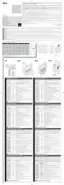
4.1 - Arranging the electrical cables to connect devices to the control unit (Table A)
Table A - Characteristics of electrical cables for the relevant connections
Device to be connected Cable cross-section Maximum cable length
/.6$124//+8%.13'$".-31.+
UNIT
B@AKDWLL
2
30 m (*1)
WARNING LIGHT WITH RADIO AN-
TENNA
B@AKDWLL
2
(for the lamp)
1&SXODRGHDKCDCB@AKDENQ@DQH@K
20 m
LQDBNLLDMCDCL
DEVICES CONNECTED TO TERMINALS
8-9-10-11-12-13
B@AKDRWLL
2
(*2) L
/.6$124//+8%.1,.3.1 B@AKDRWLL
2
10 m
(*1) l(ESGDONVDQB@AKDHRKNMFDQSG@ML@B@AKDVHSGK@QFDQBQNRRRDBSHNM@KCHLDMRHNMRHRQDPTHQDCENQDW@LOKDWLL
2
.
(*2)l3GDRDB@AKDRB@MADQDOK@BDCAX@RHMFKDWLL
2
cable.
WARNING! – The cables used must be suited to the type of environment of the installation site.
4.2 - List of control unit parts
During the successive control unit connection and programming phas-
DRSNHCDMSHEXSGDBNLONMDMSRLDMSHNMDCHM SGDSDWS QDEDQSNFig. 2
and its key.
A - Line fuse (6.3 A)
B - Connector for inserting the IBT4N interface
C f.*t+$#
D f1@CHNt+$#
E - T2 button, for memorising a transmitter and for cancelling a trans-
mitter or the entire control unit memory
F - T1 button, for programming and for sending step-by-step com-
mands
G - Dip-switch for programming the functions

 Loading...