English – 8
EN
4.4 - Connection of accessories
To connect the relevant accessories refer to Table B, to Fig. 3 and to the instruction manual of each accessory. Table B summarises all the ac-
BDRRNQHDRSG@SB@MADBNMMDBSDCSNSGDBNMSQNKTMHSSDQLHM@KR@MCSGDRODBHjB@SHNMRENQL@JHMFSGDDKDBSQHB@KBNMMDBSHNMRBefore proceeding,
carefully read the table and its notes. Note – Due to the fact that certain inputs offer different functions for connecting the accessories, once the
BNMMDBSHNMRG@UDADDML@CDHSVHKKADMDBDRR@QXSNRDSSGDCHORVHSBGDR@BBNQCHMFSNSGD@BBDRRNQHDRBNMMDBSDCRDD"G@OSDQ/QNFQ@LLHMF
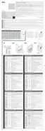
Table B%TMBSHNMNESGDSDQLHM@KRHMOTSR@MCNTSOTSR
Terminals Description of the function
1 - 2 OutputENQk@RGHMFV@QMHMFKHFGS@SSGDL@HMRUNKS@FD
3 - 4 - 5 Output for controlling the motor (open, common, close).
6 - 7 Input of the power supply line coming from the mains (live, neutral).
8 Reference to 0 V for the “"NLLNMtBNMCTBSNQNESGDCDUHBDRBNMMDBSDCSNSDQLHM@KR9, 10, 11, 12 and 13.
9 24 V output..TSOTSENQCDUHBDRENQDW@LOKDOGNSNBDKKRVHSG5
ONVDQRTOOKXKNVUNKS@FDL@WHLTLBTQQDMSCQ@VL
10 Photo test output. 24 V
outputENQ@SQ@MRLHRRHNMOGNSNBDKK37NQENQ@fCNNQNODMHMCHB@SNQKHFGStETMBSHNM,@WHLTLBTQQDMSCQ@VL
11 Stop input. Input ENQR@EDSXCDUHBDRVHSGJ´jWDCQDRHRSNQRDMRHSHUDDCFDDSB
12 SbS input. Input for a normally open (NO) button, for sending commands in step-by-step mode.
13 Photo input. Input for a normally closed (NC) reception photocell (RX), or for a normally open (NO) button.
14 - 15 Input for an antenna-radio receiver.
+RZWRPDQDJHWKHq3KRWRWHVWrRXWSXWDQGWKHq6WRSrq6E6rDQGq3KRWRrLQSXWV
4.5.1 - Photo test output (terminal 10)
3GHRNTSOTSLTRSADBNMjFTQDCSGQNTFGOQNFQ@LLHMFCHORVHSBG7CDODMCHMFNMSGDSXODNECDUHBDBNMMDBSDCHE@SQ@MRLHRRHNMOGNSNBDKK37
HRBNMMDBSDCSGDCHORVHSBGLTRSADRDSSN.-HEHMRSD@C@fCNNQNODMHMCHB@SNQKHFGStHRBNMMDBSDCSGDCHORVHSBGLTRSADRDSSN.%%
NOTESq(E@fCNNQNODMHMCHB@SNQKHFGStHRBNMMDBSDCSNSGHRNTSOTSSGD37OGNSNBDKKLTRSADBNMMDBSDCSNSDQLHM@K9. • The “door open indica-
SNQKHFGStRHFM@KRG@UDSGDENKKNVHMFLD@MHMFR
light off = door closed; light on = door open; RKNVk@RGHMF = door in opening phase; E@RSk@RGHMF = door in closing phase.
4.5.2 - Stop input (terminal 11)
3GHRHMOTSLTRSADBNMjFTQDCSGQNTFGOQNFQ@LLHMFCHORVHSBGDR1 - 2 depending NMSGDSXODNECDUHBDBNMMDBSDC normally closed (NC) con-
S@BSRMNQL@KKXNODM-.BNMS@BSRNQjWDCQDRHRS@MBDJƄBNMS@BSR Warning!.MKXSGDTRDNE@jWDCQDRHRS@MBDBNMS@BSSNFDSGDQVHSG
SGD.%%.%%RDSSHMFNECHORVHSBGDR1 - 2 guarantees the minimum level of resistance against faults, requested by the regulations. Normally the

 Loading...