6
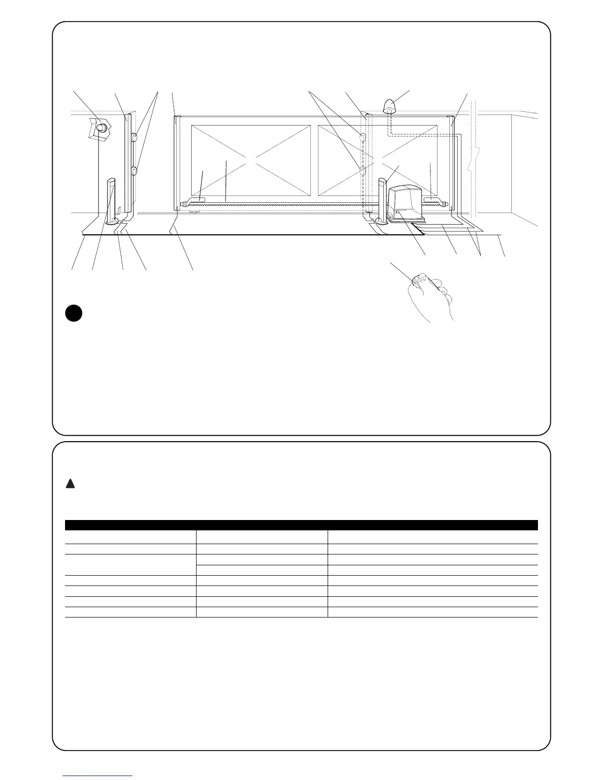
2.2) Typical system
Figure 2 shows a typical system for automating a sliding gate using ROBUS
2
1 Key-operated selector switch
2 Photocells on post
3 Photocells
4 Main fixed edge (optional)
5 Main movable edge
6 “Open” stop bracket
7 Rack
8 Secondary fixed edge (optional)
9 Flashing light with incorporated aerial
10 ROBUS
11 “Closed” stop bracket
12 Secondary movable edge (optional)
13 Radio-transmitter
2.3) List of cables
Figure 2 shows the cables needed for the connection of the devices in a typical installation; table 5 shows the cable characteristics.
The cables used must be suitable for the type of installation; for example, an H03VV-F type cable is recommended for indoor
applications, while H07RN-F is suitable for outdoor applications.
Note 1: power supply cable longer than 30 m may be used provided it has a larger gauge, e.g. 3x2,5mm
2
, and that a safety grounding sys-
tem is provided near the automation unit.
Note 2: If the “BLUEBUS” cable is longer than 30 m, up to 50 m, a 2x1mm
2
cable is needed.
Note 3: A single 2x0,5mm
2
cable can be used instead of two 4x0,5mm
2
cables.
Note 4: Please refer to Chapter “7.3.2 STOP Input” in situations where there is more than one edge, for information about the type of con-
nection recommended by the manufacturer.
Note 5: special devices which enable connection even when the leaf is moving must be used to connect movable edges to sliding leaves.
Connection Cable type Maximum length allowed
A: Power line 1 3x1,5mm
2
cable 30m (note 1)
B: Flashing light with aerial 1 2x0,5mm
2
cable 20m
1 RG58 type shielded cable 20m (recommended less than 5 m)
C: Photocells 1 2x0,5mm
2
cable 30m (note 2)
D: Key-operated selector switch 2 2x0,5mm
2
cable (note 3) 50m
E: Fixed edges 1 2x0,5mm
2
cable (note 4) 30m
F: Movable edges 1 2x0,5mm
2
cable (note 4) 30m (note 5)
Table 5: List of cables
2
43 38
10
2
6
11
7
9
13
1251
EC F
D
C
F
A
B

 Loading...