9
GB
3.5) Electrical connections
Only carry out electrical connections once the electric-
ity supply to the system has been switched off.
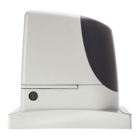
1. Remove the protection cover in order to access the electronic
control unit of the RUN. The side screw must be removed, and
the cover lifted upwards.
2. Remove the rubber membrane sealing off the two holes for routing
the cables; insert the power cable in the smaller hole and all other
cables for the various devices in the larger hole, leaving a length of
20÷30 cm longer than necessary. See Table 5 for information
regarding the type of cables and Figure 2 for the connections.
3. Use a clamp to collect together and join the cables routed through
the larger hole and place the clamp under the cable entry hole.
Make a hole in the rubber membrane which is slightly smaller than
the diameter of the cables joined by the clamp, and slide the
membrane along the cables until it reaches the clamp. Then put
the membrane back in its seat. Place a second clamp for collect-
ing the cables which are set just above the membrane.
4. On the smaller membrane, cut a hole slightly smaller than the
diameter of the power cable and slide the membrane along the
cable until it fits into its seat.
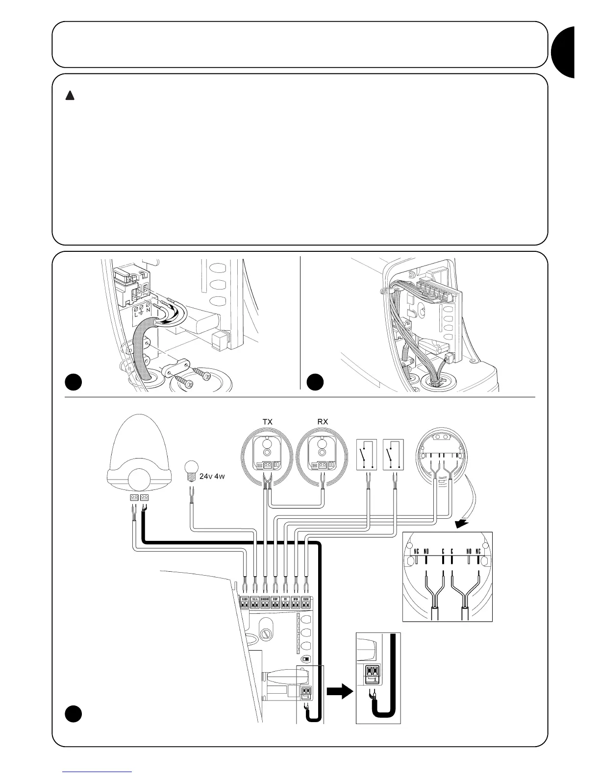
5. Connect the power cable to the relative terminal as shown in fig-
ure 14, and secure the cable by means of the collar.
6. Connect up the other cables according to the diagram in Figure 16.
The terminals can be removed in order to facilitate this procedure.
7. Once the connections have been completed, secure the cables
joined in the clamps to the cable locking rings. The excess aerial
cable must be secured to the other cables using another clamp as
shown in Figure 15.
3.4) Installation of the various devices
If other devices are required, install them following the directions provided in the corresponding instructions. Check this in paragraph “3.6
Description of electrical connections” and the devices which can be connected to the RUN in Figure 2.
14
16
15
See paragraph “7.3.5 RUN in Slave mode” for the connection of 2 motors on opposite leaves.
LUCYB
S.C.A.
MOFB MOSE
OPEN CLOSE
 Loading...