English – 5
EN
BASIC PROGRAMMING
It is necessary to set and store the most important parameters
before putting the loading ramp into operation.
Keep the
Ramp button pressed and at the same time enable the
main switch to enter the basic Programming mode.
After about 4 seconds the message 026 appears on the display;
now also press the button
R
. After pressing the button
R
, release
the button
and then also release button
R
.
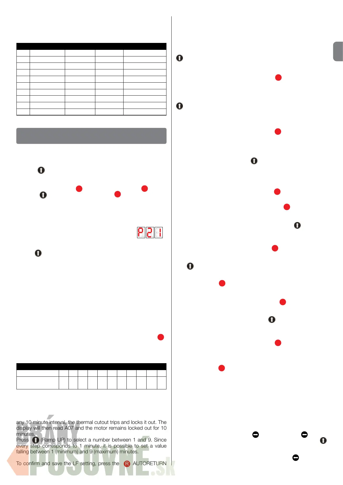
Now the version of the program also briey appears on the display,
followed by the set valve program (P1, P2, etc.) and/or by the
appropriate test Program.
Use the Ramp button to set the loading ramp type:
P11/P12 = ramp with hinged lip
(P12 = Ramp UP does not use the valve)
P13 = ramp with hinged lip (2 valves), automatic Ramp
DOWN
P21/P23/P25 = ramp with telescopic lip (2 valves), automatic
Ramp DOWN
P31 = ramp with telescopic lip (3 valves), automatic
Ramp DOWN
P32/P33 = forced Ramp DOWN
(P33 = hold-to-run)
When the correct loading ramp type is displayed, press button
R
to conrm (memorize).
You now enter conguration mode; the parameters display in
sequence. The sequence depends on the type of ramp, as follows:
Table 2
P11-P12-P13 LF LE LA LN LR RB LC AR PC BU x
P21-P23-P25-
P31-P32-P33-TST
LF LE LA LN LR RB LC AR PC BU LL
The display now shows LF0.
This sets the hydraulic motor thermal protection - i.e. its maximum
use over a period of ten minutes; the default setting is 1 minute, so
that if the motor is run for 1 minute (even not continuously) within
any 10 minute interval, the thermal cutout trips and locks it out. The
display will then read A07 and the motor remains locked out for 10
minutes.
Press
(Ramp UP) to select a number between 1 and 9. Since
every step corresponds to 1 minute, it is possible to set a value
falling between 1 (minimum) and 9 (maximum) minutes.
To conrm and save the LF setting, press the
R
AUTORETURN
OPERATION WITHOUT CUSTOMISATION MODULE
button.
The display now shows LE0.
If the ramp is tted with a telescopic lip, this parameter sets the
minimum lip extension time. The main purpose of this setting is to
protect the legs supporting the lip (if present) against collision with
the base of the ramp itself. The basic time setting is 500 ms. Press
(Ramp UP) repeatedly to set a value of 1 to 9. Since every step
corresponds to 200 ms, it is possible to set a value falling between
500 ms (minimum) and 2.3 seconds (maximum).
To conrm and save the LE setting, press
R
AUTORETURN.
The display now reads LA0.
If the ramp is tted with a telescopic lip, this parameter sets the
maximum lip extension time; the default setting is 5 seconds. Press
(Ramp UP) to set a value of 1 to 9.
Since every step is equal to 1.5 seconds, it is possible to set a time
between 5 seconds (minimum) and 18.5 seconds (maximum).
To conrm and save the LA setting, press
R
AUTORETURN.
The next parameter is Ln0.
Here the maximum time of the difference between the retract and
extend movements of the telescopic lip is dened; the set basic time
is 0.5 seconds. By pressing the
(Ramp UP) button repeatedly,
now it is possible to select a number between 1 and 9. Since every
step corresponds to 0.5 seconds, it is possible to set a value between
0.5 seconds (minimum) and 5.0 seconds (maximum) hinged lip 2*Ln
on 1*Ln down).
To conrm and save the Ln setting, press
R
AUTORETURN.
The display now reads Lr0.
Lr is the ramp DOWN time in mode 00E
when
R
AUTORETURN
is pressed in 00E mode. In detail, it is the time employed by the
ramp in travelling from its maximum height to its standby position
(fully down). The basic time set is 5 seconds. Press
(Ramp UP)
repeatedly to set a value of 1 to 9. Since every step is equal to 1
second, it is possible to set a value between 5 seconds (minimum)
and 14 seconds (maximum).
To conrm and save the Lr setting, press
R
AUTORETURN.
We now set rb0.
Use
(Ramp UP) to select a value between rb0 and rb9, where
rb0 = gate deactivated and rb1-rb9 = gate active (with a gate active
time equal to the setting times 5, e.g. 9x5 = 45 seconds). To save
the setting, press
R
AUTORETURN.
The display now reads Lc0.
Lc is the Ramp UP time in mode 00C when
AUTORETURN is
pressed. In detail, it is the time employed by the ramp in travelling
from its minimum height to its standby position (fully down).
The basic time set is 3 seconds. Press
(Ramp UP) repeatedly
to set a value of 1 to 9. Since every step (number) corresponds to 1
second, it is possible to select a time between 3 seconds (minimum)
and 12 seconds (maximum).
To conrm and save the Lc setting, press
R
AUTORETURN.
The display now reads Ar0.
Ar can be set to either 0 or 1. These settings indicate the lack /
presence of the
R
AUTORETURN button on the control unit,
respectively. Do not modify the default setting.
The display now reads Pc0.
Pc has different functions depending on the type of ramp in use.
Ramps with hinged lip [P11 / P12 / P13]: Pc takes a value from 0 to
9 and indicates the sensitivity of the current measurement used to
detect the position of the lip while it is opening. It is used to detect
malfunctions during technical service and should not be modied.
Ramps with telescopic lip [P21 / P23 / P25 / P31 / P32 / P33]: Pc
affects the behaviour of the ramp and lip in the oating position 00A.
Pc0 the lip is locked since the
(extend lip) and (retract
lip) are disabled. To move it, you must rst raise the ramp with
(Ramp UP)
Pc1 the lip can always be extended or retracted, there is no need to
raise the ramp rst. The operation starts by pressing
(retract lip).
Pc2-Pc9 the lip can always be extended or retracted, but the ramp
The following table illustrates the valve versions and their
operation for each type of ramp.
1,2,3 = number of valve
M = motor
Table 1
Ramp UP Extend Retract Ramp down
P11 1+M 1
P12 M 1
P13 1+M 1+M 1+2+M 1
P21 1+M 2+M M 1+2
P23 2+M M 2+M 1
P25 1+M M 1+M 2
P31 1+M 2+M 3+M 1
P32 1+M 2+M 3+M 1
P33 1+M 2+M 3+M 1
 Loading...