6 – English
EN
OPERATION WITH CUSTOMISATION MODULE
CUSTOMISATION MODULE [PEEP] CONNECTION
If the ramp is operated with one of the
options given below, you must mount
a customisation module [PEEP] to socket Y8
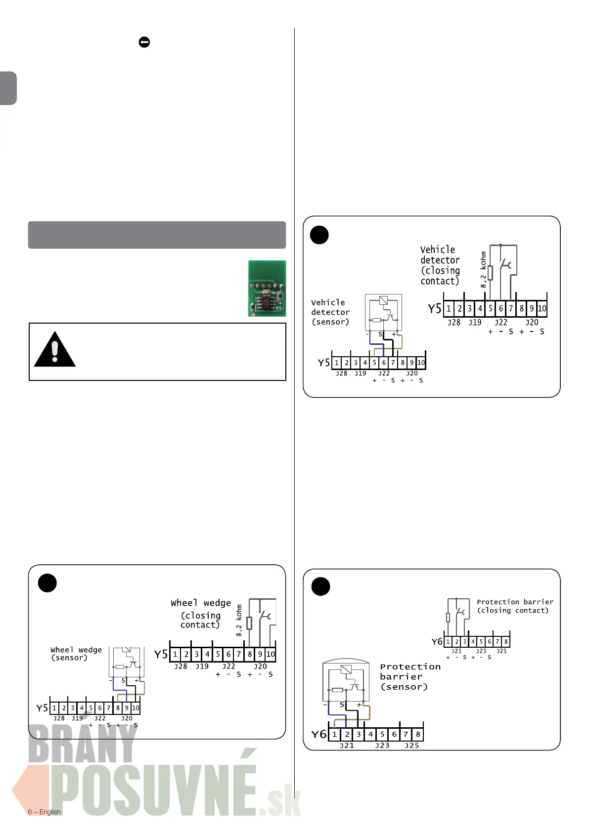
Wheel chock connection - [option 1 (o1)] - g. 12
If the option (o1) is selected with the PEEP module, after coupling
the vehicle it is necessary to put the chock under the rear wheel
. If
you use the external trafc lights option (o4), the RED light trips after the
chock is inserted. Then it is possible to control the loading ramp system
(shelter, door, loading ramp).
If you use a microswitch (closing contact), terminals Y5/8 (J20 +) and
Y5/10 (J20 S) produce an 8.2 kOhm resistance. The microswitch
(closing contact) is connected to terminals Y5/9 (J20 -) and Y5/10
(J20 S).
If you use an electronic sensor, the brown wire of the sensor (+) is
connected to terminal Y5/8 (J20 +), the blue wire (-) to terminal Y5/9
(J20 -) and the black wiring wire (S) to terminal Y5/10 (J20 S).
Caution!
If the customisation module was enabled
once on the plant, it cannot be used on
another plant afterwards!
Vehicle detector connection - [option 2 (o2)] - g. 13
If you use a vehicle detector with microswitch (switching contact),
the opening contact is connected to terminal Y5/5 (J22 +), the
closing contact to terminal Y5/6 (J22 -) and the common contact
(COM) to terminal Y5/7 (J22 S).
If you use a microswitch (closing contact), terminals Y5/5 (J22 +)
and Y5/7 (J22 S) produce an 8.2 kOhm resistance. The microswitch
(closing contact) is connected to terminals Y5/6 (J22 -) and Y5/7
(J22 S).
If you use an electronic sensor, the brown wire of the sensor (+) is
connected to terminal Y5/5 (J22 +), the blue wire (-) to terminal Y5/6
J22 -) and the black wiring wire (S) to terminal Y5/7 (J22 S).
If option 2 is set on 1, option 9 then appears on the Fd display
(alternative vehicle detector). 0 = standard, 1 = rest position, 2 =
start shelter vehicle detector!
Forced lowering connection
(Protection barrier/special software) - [option 3 (o3)] - g. 14
If you use a protection barrier with microswitch (switching contact),
the opening contact is connected to terminal Y6/1 (J21 +), the
closing contact to terminal Y6/2 (J21 -) and the common contact
(COM) to terminal Y6/3 (J21 S).
If you use a microswitch (closing contact), terminals Y6/1 (J21 +)
and Y6/3 (J21 S) produce an 8.2 kOhm resistance. The microswitch
(closing contact) is connected to terminals Y6/2 (J21 -) and Y6/3
(J21 S).
If you use an electronic sensor, the brown wire of the sensor (+) is
connected to terminal Y6/1 (J21 +), the blue wire (-) to terminal Y6/2
(J21 -) and the black wiring wire (S) to terminal Y6/3 (J21 S).
13
Connection - vehicle detector
14
Connection - protection barrier
rst raises automatically by (2...9) x 100ms = 200ms...900ms. The
operation starts by pressing
(retract lip).
The display now reads Bu2.
Bu indicates the control box button conguration, and can take the
following values:
2 - single button conguration.
3 - standard conguration.
4 - forced ramp down in single-valve systems. See paragraph
Forced lowering connection.
Do not modify the default setting of Bu.
The display now reads LL5.
LL indicates the length of the telescopic lip, and can take the
following values:
5 - for 500mm lips.
1 - for 1000mm lips. In this case, the time associated with parameter
LA is doubled.
12
Connection - wheel chock
 Loading...