English – 7
EN
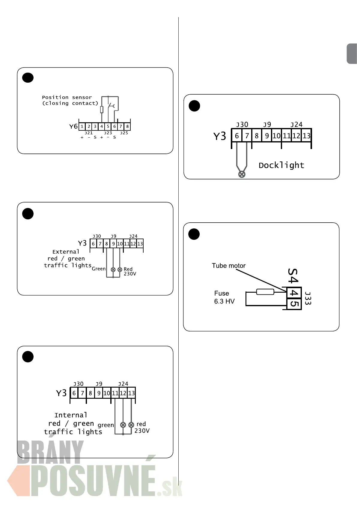
EXTERNAL TRAFFIC LIGHTS connection - [option 4 (o4)] - g.
16
The red trafc lights are connected to terminal Y3/12 (J24), the green
trafc lights to terminal Y3/13 (J24) and the common N conductor to
terminal Y3/11 (J24).
Connecting the loading ramp position sensor
(special software) - g. 15
If you use a microswitch (closing contact), terminals Y6/4 (J23 +)
and Y6/6 (J23 S) produce an 8.2 kOhm resistance. The microswitch
(closing contact) is connected to terminals Y6/5 (J23 -) and Y6/6
(J23 S). It is necessary to remove the jumper between terminals
Y6/5.6 if a position sensor!
15
Connection - closing contact position
sensor
16
Connection - external RED/GREEN
trafc light
INTERNAL TRAFFIC LIGHTS connection - [option 5 (o5)] - g.
17
The red trafc lights are connected to terminal Y3/9 (J9), the green
trafc lights to terminal Y3/10 (J9) and the common N conductor to
terminal Y3/8 (J9).
17
Connection - internal RED/GREEN
trafc light
Connecting the loading ramp docklight - [option 6 (o6)] - g.
18
If option (o6 ) is selected and the docklight is installed, the docklight
switches ON and OFF again during ramp movement when the ramp
returns to the rest position.
The docklight can be connected to terminals Y3/6,7 (J30).
CAUTION - max. 500W !!!
Connecting the 6.3 AT external fuse for the docklight or the
internal/external TRAFFIC LIGHT g. 19
18
Connection - loading ramp docklight
Terminals S4 (J33) can be used for connecting an external 6.3 AT
fuse for the trafc light or docklight.
Horn connection - [option 7 (o7)]
If option (o7) is selected in the PEEP module, in the event of error
19
Connection - 6.3 AT fuse for docklight
or internal/external trafc light
the alarm horn trips. It is necessary to switch off the voltage using
the main switch to disable the horn. The alarm horn plug must be
connected to the Y10 socket!
Shelter connection - g. 20 [option 8 (o8)] with UDL-E1 plug
module
Y3-1 = L1 mains voltage for tubular and supercharged motors
Y3-2 = N mains voltage for tubular and supercharged motors
Y3-3 = shelter option
Y3-4 = shelter option
Y3-5 = shelter option
Y3-6 = N supercharged motor
Y3-7 = L1 supercharged motor
Y11-1 = sensor signal (reserve)
Y11-2 = GND sensor (reserve)
Y11-3 = +24V sensor (reserve)
Y11-4 = shelter sensor signal
Y11-5 = GND shelter sensor
Y11-6 = +24V shelter sensor
If option 8 is set on 1, option 9 displays and then Sh (shelter option).
Now it is possible to set the shelter control functions (ON/OFF).
0 = automatic operation disabled - the shelter can be activated/
 Loading...