8 – English
EN
20
1 2 3 4 5 6 7
h
h
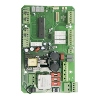
Plug module UDL-E1
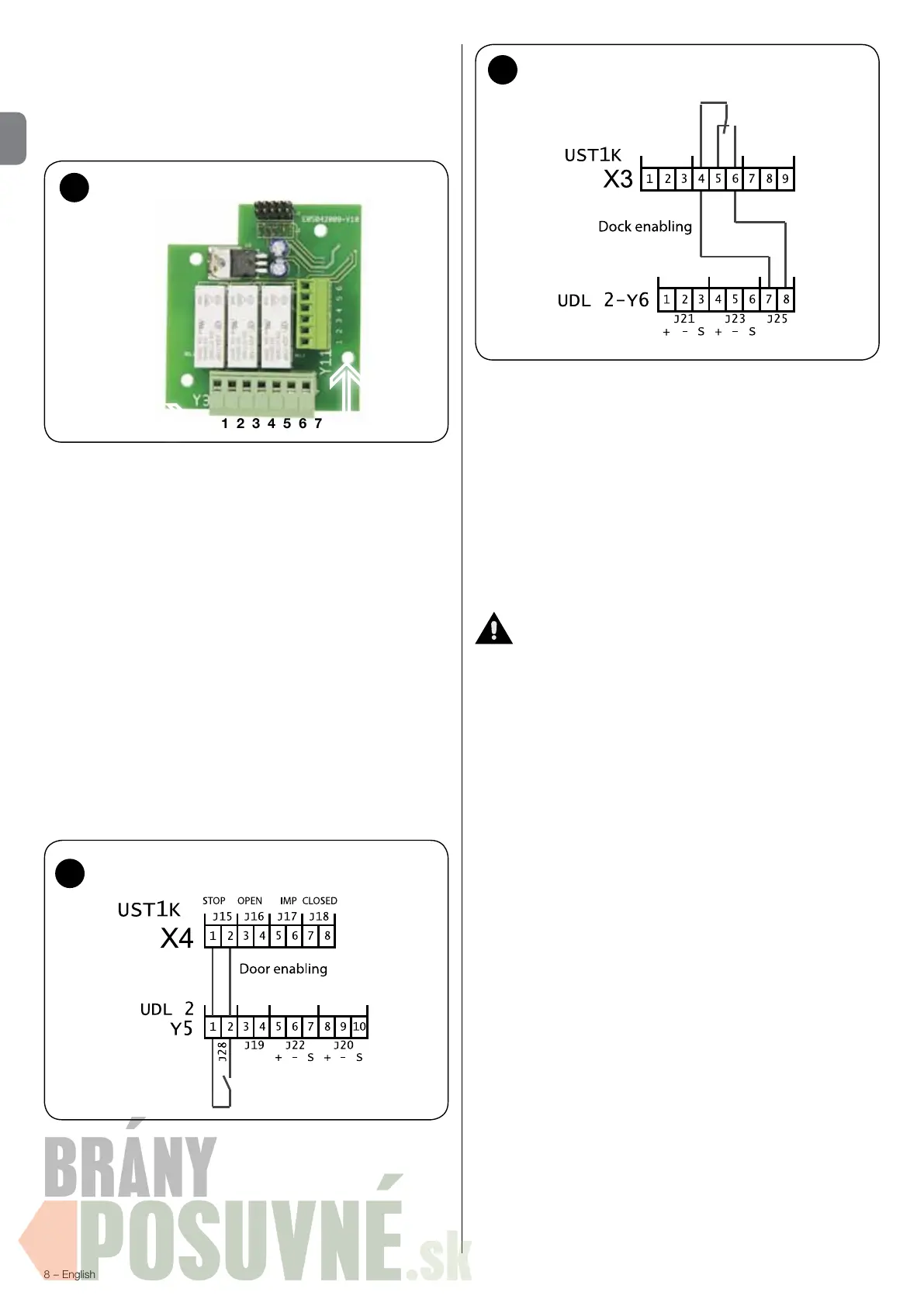
Door connection [option 9 (o9)] - g. 21-22
if the ramp system is connected to an electromechanically actuated
door, the door lock [0V contact UDL 2] terminal Y5/1,2 (J28) must
be connected to the STOP X4/1,2 (J15) terminal on the D-Pro
Automatic, while a 0V contact of the D-Pro Automatic, terminal
x3/4,6, must be connected to terminals Y6/7,8 (J25) of the UDL
2 [ramp enable]. With these two connections the door with electric
operation and the ramp system are reciprocally blocked.
Caution! - In the rmware of 900 series models, option 9 takes three
values:
0 - interlocking disabled;
1 - standard interlocking enabled;
2 - partial interlocking enabled.
In partial interlocking the direction followed is that of door --> ramp.
Along with setting o9=2, in this case you must also remove the
connection between terminal Y5/1,2 (J28) on the UDL2 and the
STOP terminal, X4/1,2 (J15), of the D-Pro Automatic, and jumper
the latter. This means that the door is always enabled while the ramp
is only enabled when the door is fully open. In other words, the ramp
cannot be moved while the door is moving up or down or when it
is closed.
Service LED connection
The service LED connector must be connected to terminal Y11
of the board. A service counter for 1000 cycles is enabled in the
memory of the loading ramp control unit; when the 1000 cycles are
reached, the service LED starts to slowly ash with the loading ramp
in rest position. Contact the assistance service to reset the service
counter.
The service LED starts to slowly blink for any other failure, while it
remains permanent red when the ramp deck is oating.
Connection of control elements built into the cover
The plug of the control elements must be connected to the Y7
socket!
Caution! - DOOR LIMIT SWITCH SETTING
If you use the UDL 2 with a D-Pro Automatic, to set the limit switches
you must disconnect the X4/1,2 connection and replace it with a
jumper (see the limit switch conguration instructions)!
Remove the electrical jumper and connect the two wires again
(connection to the UDL 2) when the limit switches are set!
22
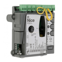
Connection - D-Pro Automatic door
21
Connection - D-Pro Automatic door
deactivated at any time with the Start / Stop button
1 = the shelter must be activated (Start/Stop button) so long as the
ramp is enabled to move, and the door must be open (if interlocking
is present)
2 = the shelter is activated/deactivated automatically when the door
opens/closes (or after delay Rb has expired)
 Loading...