Pump
B 2-17
E 2000 Nordson Corporation
All rights reserved
41-3000
Issued 11/00
B2EN-02-[3-PUMP]-5
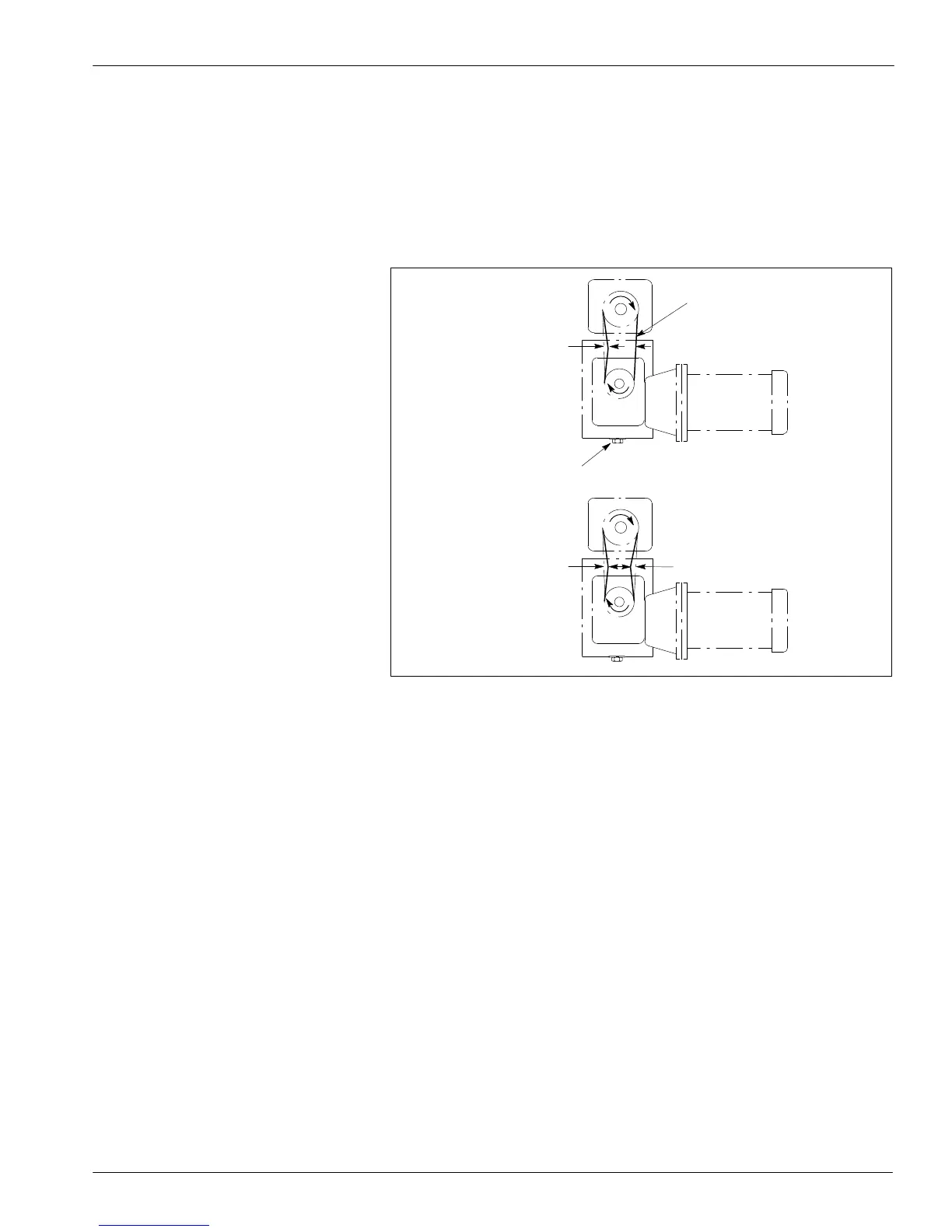
c. Tighten the screws again and recheck the chain tension.
Continue this process until tension/deflection matches the
dimensions shown in Figure B 2-5 when all four speed reducer
screws are tight. Tighten the screws to 6.78–8.14 NSm (5–6 ft-lb).
Lock the chain-tensioning screw nut.
d. Recheck the speed reducer sprocket. Make sure the sprocket is
level with the drive shaft sprocket.
4130914A
1
2
4.1–5.8 mm
(0.16–1.23 in.)
2.0–2.9 mm
(0.08–0.12 in.)
2.0–2.9 mm
(0.08–0.12 in.)
Fig. B 2-5 Chain Tension/Deflection
1. Chain-tensioning screw 2. Tight chain
7. Reinstall the hopper and drive covers.
8. Restore the system to normal operation.

 Loading...


