54
Description
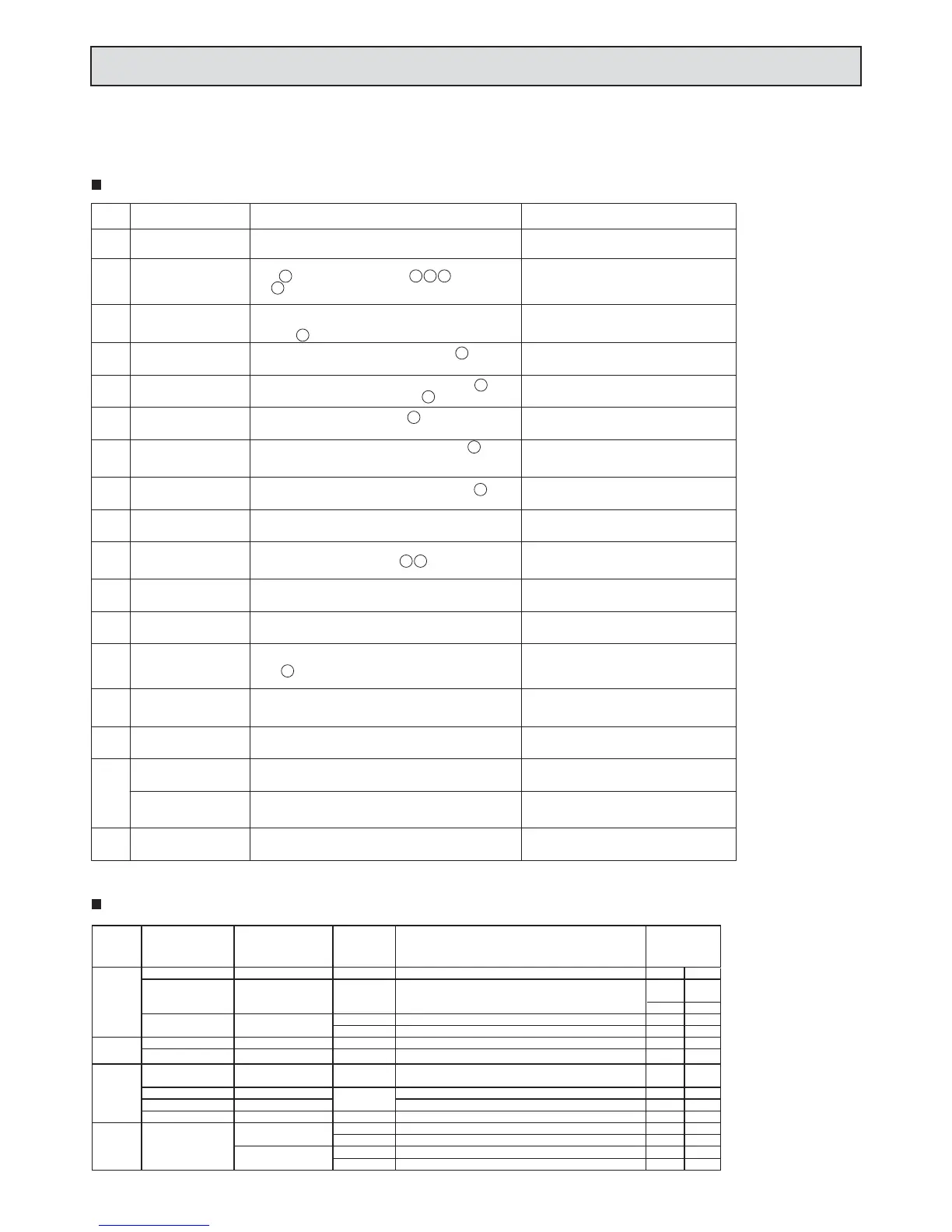
Ignition Failure
(Initial Flame Fault
detection)
Flame Rod Does Not
Detect Flame (Secondary
Flame Fault Detection)
Thermal Fuse
Triggered
Abnormally High Output
Temperature
High Limit SwitchTriggered.
Inlet Thermistor
Abnormality
Outlet Thermistor
Abnormality
Fan Motor Abnormality
Heat Exchanger Flow
Abnormality
Check for scale build-up in heat exchanger. Check for
abnormal combustion. Check ue blockage or obstruction.
Check that ame ignites all across the burner.
Circuit board Abnormality
Gas Solenoid Valve Drive
Circuit Abnormality
Remote Controller
Transmission Abnormality
Circuit board setting abnormality
(High elevation connector,
dipswitch, etc)
Combustion Abnormality
(Warning Indication)
Combustion Abnormality
(Unit Shuts O)
Flame Rod circuit
Abnormality
(Detection of Flame when
no ame is present)
Combustion Abnormality
(BTU Drop)
(Unit Continues Working)
Display
10
11
12
14
16
20
31
32
61
59
70
71
72
73
90
99
760
To reset this error code, the power needs to
be diconnected and then reconnected.
To reset this error code, the power needs to
be disconnected and then reconnected.
To reset this error code, the power needs to be
disconnected and then reconnected.
To reset this error code, the power needs to be
disconnected and then reconnected.
To reset this error code, the power needs to
be disconnected and then reconnected.
Check for abnormal combustion.
Check ue for blockage or obstruction.
Check for melting or damage to the thermal fuse ( ).
Check for improper connection of thermal fuse.
Check if high limit switch is triggered ( ). Check for
improper connection of high limit switch.
Measure the resistance through the inlet thermistor ( ).
Check for an open or short circuit. Check for improper
connection to the inlet thermistor.
Check that the fan is rotating. Check the pulse frequency from
the fan rotational frequency sensor ( ). Check for improper
connection of the fan. Check voltage from circuit board.
Check for damage to the gas solenoid vavle drive circuit on
the circuit board.
Measure the current from the ame rod when there is no
ame ( ). Check for a ground fault.
Check connection from remote controller to circuit board.
Check remote controller and circuit board for damage.
Check for abnormal combustion.
Check ue for blockage or obstruction.
Measure the resistance through the outlet thermistor ( ).
Check for improper connection or an open or short circuit.
Check gas supply piping and pressure. Check for igniter
spark ( ). Check gas solenoid valves ( ). Check ame
rod ( ). Check ground, paying special attention to the ground
connection to the circuit board.
12
1
11
13
3
4
6
7
5
Note 1)
Note 1)
Note 1)
Note 1) This error code is not mentioned in the owchart.
Check for abnormal combustion.
Check ue for blockage or obstruction.
Check that ame ignites all across the burner.
Combustion abnormality
(Unit Shuts O)
Check for abnormal combustion.
Check ue for blockage or obstruction.
Check for proper setting of maintenance writers on circuit board.
Check the circuit board (microcomputer) for damage. Check the
Dip switch. Check the "Control switch connector"
(ex. high elevation connector etc.).
8. Troubleshooting
Error Codes and Checkpoints (With optional remote controller connected)
<NR50-OD / NR66 (-SV,-OD) / N-0531S (-OD), NR71 (-SV,-OD) / N-0631S (-OD)>
Error Codes and Checkpoints for NR71/N-0631S Series Only (No remote controller connected)
No. of
Flashes
Reset Method
(without Remote
Controller)
Will Unit
Work After
Being Reset
Other Symptoms
No Reset
YES
It's available to burn even before reset.
It's available to burn even before reset.
10
90
11
12
72
73
90
59
16
If minimum ow rate is available immediately
61
If power button is on immediately
32
20
72
71
99
NO
70
Error Code
Representation
NO
NO
NO
5
4
3
Contin-
uous
Flashing
Disconnect Power
Disconnect Power
Turn O Water
Reset Method
(with Remote
Controller)
Turn O Water
Disconnect Power
Turn O Water Turn O Water
Turn O Water
Disconnect Power
Disconnect Power
Disconnect Power
Disconnect Power
Power Button
Power Button
Turn O Water
Power Button
Power Button
Turn O Water
YES
YES
YES
YES
YES
YES
YES
Turning o the water will only reset the unit if there
is no remote controller installed.
If minimum ow rate is available immediately
When adjusting the manifold gas pressure, be sure to remove the exhaust ue, the air inlet and the ue collar.
Diagnosis Point (Trouble Point)
Remarks
8
9
10
11
12
Check for accidental extinction of the ame. Check for
abnormal combustion, check gas solenoid valves, check
ame rod ( ). Check ground, especially on circuit board.
Measure the resistance through the outlet thermistor ( ).
Check for proportional gas valve trouble ( )
4
Circuit board failure
YES
No Reset
90
31
14
Turn O Water
 Loading...