75
Circuit Board Replacement
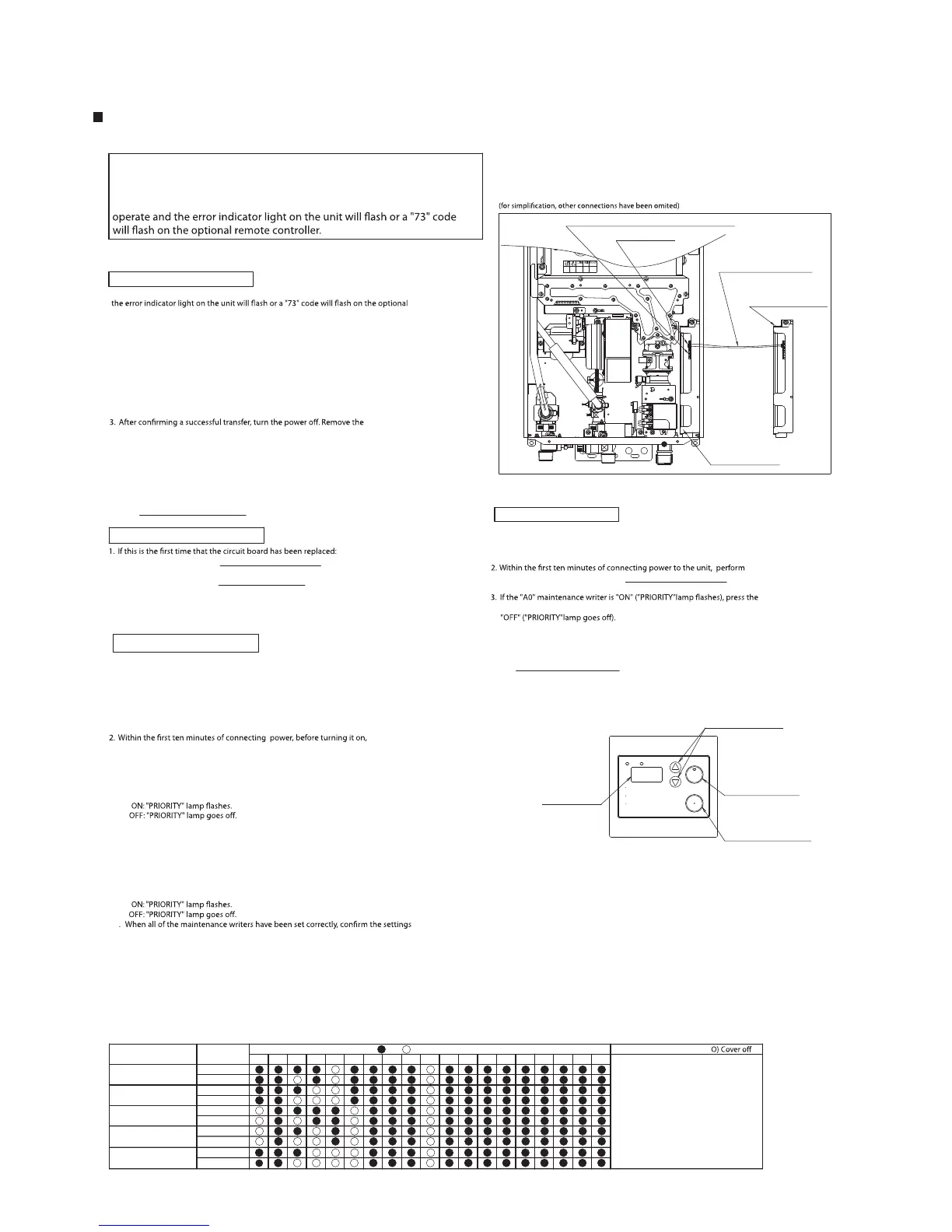
When a circuit board is replaced, data must be transferred from the old board, otherwise
remote controller and the unit will not operate.
After installing the new circuit board, please transfer data according to the following procedure:
1. With the electrical power disconnected, connect the new and old
circuit boards by inserting the supplied data transfer wire into
connection number CN75 (see Note 1) of each circuit board. If a temperature
selection wire is inserted into CN75 on the old circuit board, remove this
connector and save it for the new circuit board.
The unit will signal a successful transfer by rotating the fan and opening and closing
the gas solenoid valve (3 minutes).
cable connecting the new and old circuit boards.
4. If a temperature selection wire was removed from the old circuit board, reinsert it into CN75
on the new circuit board.
* Be sure to read.
It is necessary to transfer data when replacing a circuit board. Vital
information about the water heater such as the settings and unit history
will have to be written to the new board. Please transfer data using the
following procedure. If the transfer is not successful, the unit will not
Data Transferring Procedure
Note 1. The data transfer wire is marked "89", but please connect it to connection number CN75.
2. If this is the second time that the circuit board has been replaced:
* If data has already been transferred to the board, follow the resetting procedure.
* Once data has been transferred to a new board, the transfer procedure cannot
be performed again.
Initial Circuit Board Settings
are made before making the initial circuit board settings.
Reference connection diagram
1. Install the circuit board into the unit and make all wiring connections.
"FLOW METER ALARM SET" button for 0.5 seconds to change "A0" to
4. Press and hold both the "up" and "down" buttons on the remote controller
is not done.
the "Data Transferring Procedure".
Circuit Board Resetting
Setting Button
(Swiching ON/OFF)
Please read instructions carefully
Check actual and controller water
Hot Water Heater temperature
over 125 °F can cause severe burns
WARNING
temperature before entering shower
before using this appliance.
Display
Setting Button
DOWN
BURNER ON
PRIORITY
°
F
gal.
POWER
ON/OFF
UP
FLOW METER
ALARM SET
Operation Button
RC-7649M
or bath.
instantly or death from scalding.
1. Connect electrical power to the unit and wait ten seconds before proceeding to step 2.
hit the "up" or "down" button on the remote controller and hold until the display
blinks "99". If the unit does not go into maintenance mode, unplug the unit and
try again.
3. Use the "up" or "down" button on the remote controller to change the maintenance
5. Change "1F" from OFF to ON. (for NR50-OD, NR71 (-SV,-OD) and N-0631S (-OD) models only)
7. Change "FE" and "FC" from OFF to ON in order to access the hidden maintenance writers.
6. Change "2B" from OFF to ON.
(Display blinks with "A0".)
8. Now the maintenance writers can be accessed by hitting the "up" or "down" button
correct writer setting.
by pressing and holding both the "up" and "down" buttons on the remote controller
done.
Buttons for adjusting the manifold pressure settings
Connector Lead attached
with a New Circuit Board
for Servicing
Connector CN75
New Circuit Board
Old Circuit Board
16A
* After replacing the board, check and adjust manifold gas pressure settings to
listed in the "Setting list for Gas manifold pressures" table of the unit.
* When you cannot transfer data between the boards, please follow the procedures
Note: A remote controller may be necessary to complete the set-up
of the new circuit board.
controller before performing the below steps.
2. Reconnect the electrical power. The data transfer will be completed in about 30 seconds.
under "Data Transfer Troubleshooting".
Data Transfer Troubleshooting
Please follow the procedure "Initial Circuit Board Settings".
Please follow the procedure "Circuit Board Resetting".
* After replacing the circuit board, make sure all connections
* When the water heater has no remote controller, make sure to connect
a remote controller before performing the initial settings below.
4. Press the "FLOW METER ALARM SET" for 0.5 sec to change the setting ON/OFF.
* When the water heater has no remote controller, make sure to connect a remote
steps 1 through 4 and step 6 of the "Initial Circuit Board Settings" procedure. This
should result in "A0" blinking on the remote controller.
5. If this is a replacement board that had initial problems with data transfer, follow
until the controller emits a beeping noise. The new settings will be lost if this
[RC-7649M, RC-7650M]
(Changing Writer No.)
(Writer No.)
writer number.
on the remote controller. Refer to the "Setting list for DIP settings" table for the
9. Press the "FLOW METER ALARM SET" for 0.5 sec to change the setting ON/OFF.
10
until the controller emits a beeping noise. The new settings will be lost if this is not
Note 1. To cancel the settings, let the controller sit for 10 minutes,
or turn on the operation button. The information set previously
will be canceled. To change settings again, follow steps 1 through 9.
Note 2. Only change data as listed in the "Setting list for DIP settings" table.
Setting list for DIP settings
(check the rating plate for model and gas type)
<NR50-OD / NR66 (-SV,-OD) / N-0531S (-OD), NR71 (-SV,-OD) / N-0631S (-OD)>
Gas Type
Model
NR71-SV/N-0631S
NG
NG
LPG
LPG
A1 ABA9A7
NR71-OD/N-0631S-OD
B0 B1 B8AE
BE C3
AD B5 B7
C4C1
NR66-SV/N-0531S
NR66-OD/N-0531S-OD
NG
NG
LPG
LPG
1F 2B BCA8
Circuit board DIP setting ( :ON :OFF)
Manifold Pressure (inch H2
"Refer to Page.83 - 87"
NR50-OD
NG
LPG
 Loading...