83
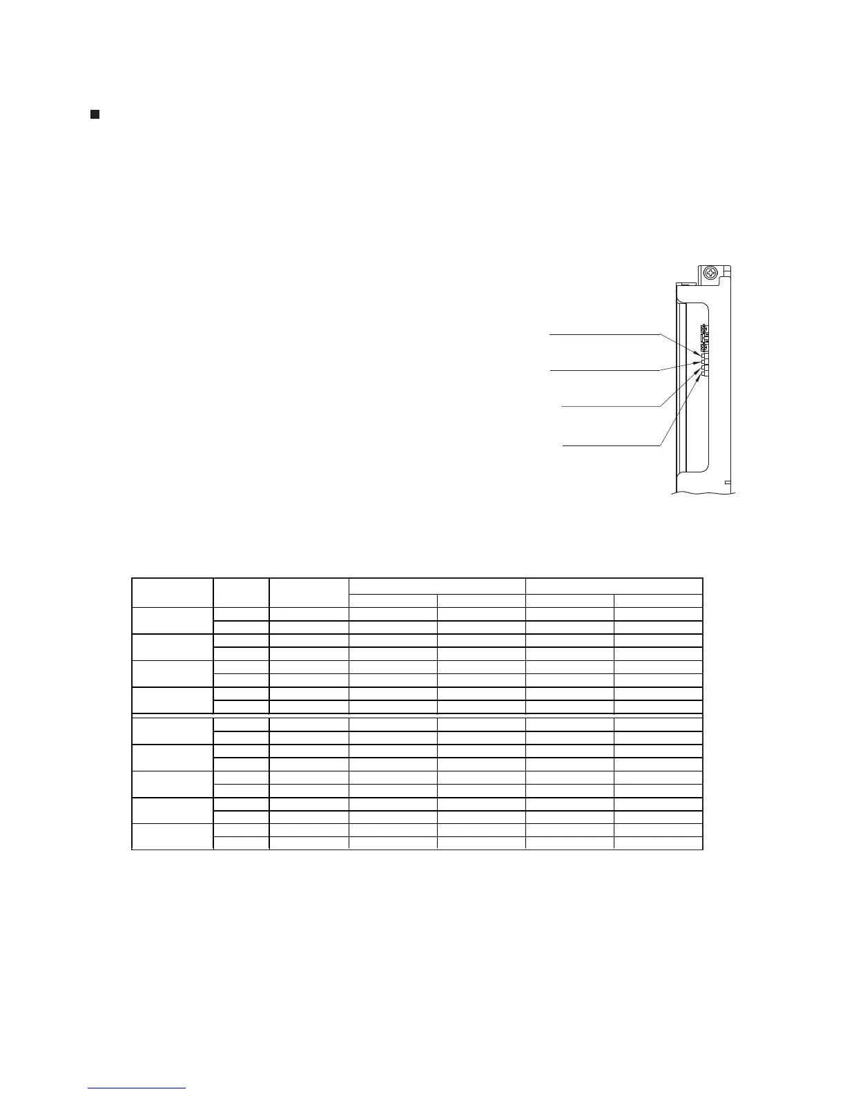
Manifold Gas Pressure Adjustment
(1) With a manometer or pressure gauge connected to the manifold pressure
tap, press and hold the maximum manifold gas pressure set button. Use the manifold
gas pressure increase and decrease buttons to adjust to the correct pressure.
(2) Press and hold the minimum manifold gas pressure set button.
Use the manifold gas pressure increase and decrease buttons
to adjust to the correct pressure.
(3) Repeat steps (1) and (2) until both are at the correct pressure.
Manifold Gas Pressure
Increase Button
Manifold Gas Pressure
Decrease Button
Minimum Manifold Gas
Pressure Set Button
Maximum Manifold Gas
Pressure Set Button
When the manifold gas pressure is adjusted, the front cover will be o. Adjust the manifold gas pressure to
the value of "Cover O" in the table (because it is not possible to adjust the manifold gas pressure with the
front cover on).
Use the following procedure to adjust the manifold gas pressure only if it can be done with a high ow rate
through the unit.
Note 2)
Note 1)
Manifold Gas Pressure Maximum and Minimum Values
t.BOJGPMEHBTQSFTTVSFWBMVFTBSFTVCKFDUUPDIBOHFXJUIPVUQSJPSOPUJDF
Please check the latest burner specication table.
Circuit Board
<NR50-OD / NR66 (-SV,-OD) / N-0531S (-OD), NR71 (-SV,-OD) / N-0631S (-OD)>
Max. Value Min. Value Max. Value Min. Value
NG 7.9 2.25 0.55 2.89 0.72
LPG 11.0 2.65 0.55 2.85 0.80
NG 7.9 2.25 0.55 3.05 0.72
LPG 11.0 2.50 0.50 3.46 0.84
NG 7.9 2.20 0.60 2.73 0.88
LPG 11.0 2.75 0.70 3.09 1.00
NG 7.9 2.20 0.60 2.69 0.88
LPG 11.0 2.80 0.70 3.09 1.00
NG 7.9 2.25 0.55 2.89 0.72
LPG 11.0 2.65 0.55 3.09 0.88
NG 7.9 2.25 0.55 3.05 0.72
LPG 11.0 2.50 0.50 3.61 0.84
NG 7.9 2.20 0.60 2.77 0.88
LPG 11.0 2.75 0.70 3.46 1.09
NG 7.9 2.20 0.60 2.77 0.84
LPG 11.0 2.80 0.70 3.46 1.09
NR66-OD
Manifold Pressure (inch H
2
0) Cover o
Manifold Pressure (inch H
2
0) Cover on
Supply Pressure
(inch H
2
0)
N-0631S-OD
N-0531S
N-0531S-OD
NR71-SV
NR71-OD
NR66-SV
Model Gas Type
N-0631S
NG 7.9 2.63 0.96 2.81 1.04
LPG 11.0 3.05 0.92 3.26 1.00
NR50-OD
 Loading...