1-94
Installation 15088:K 3/21/01
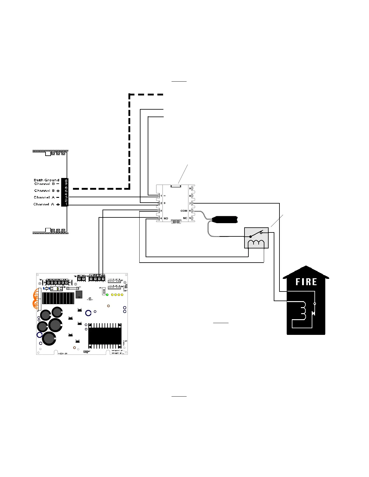
Fire Alarm polarity shown!
P2
This CMX must be programmed as:
Software Type ID GAS
Address L1M97
SLC LOOP Channel A
off Loop Interface
Board Number 1
LIB-200
LIB-200A
LIB-400
Listed
Power Supervision Relay
(Contacts shown in
energized position)
Do not
break tabs!
White Wire
Brown Wire
Black Wire
CMX
MBT-1
Figure 6.1-1 Auxiliary Fire Alarm System
(Fire Alarm Signal Transmission)
Section 6.1 NFPA 72 Auxiliary Fire Alarm Systems
MPS-24A
24V DC Common
NOTE
Wiring between the MBT-1 and the Municipal Box cannot exceed 1000 meters (1093 yards), it must not cross any
power lines and must not be in the vicinity of any high voltage.
NOTE
10 ohms maximum loop resistance wiring
from power supply to municipal box.
For connection of initiating devices and modules in this system, refer to Figures 4.6-2 through 4.6-6. This
application is not suitable for separate transmission of sprinkler supervisory or trouble conditions. For additional
ratings, refer to Appendix A.
NOTE
During programming, NFPA menu option "72B" must be chosen.
Connect wires to two
red terminals on box
Braided-shield/Drain Wire
+ To next device
- on SLC Loop
Gamewell
Model M34-56
Local Energy
Municipal Box
Red Wire
 Loading...


