NFS-320/E/C Installation Manual — P/N 52745:M2 7/1/14 13
System Components System Overview
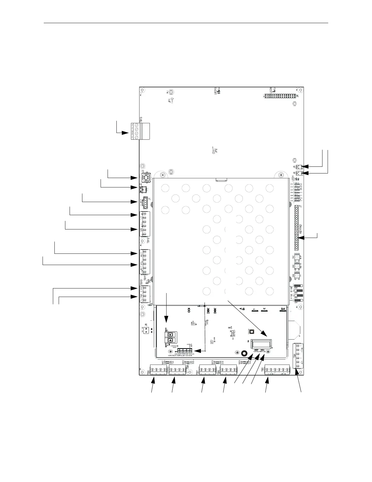
2.2.4 Circuit Board Components
The following three figures illustrate the location of the various connections, switches, jumpers and
LEDs on the NFS-320 and its power supply. Figure 2.2 shows wiring connections; Figure 2.3
shows jumpers, LEDs and switches. See Section 3 “Installation” for larger images and more details.
(Larger images are referenced on these drawings.)
TB13 - SLC Loop #1
(supervised, power-
limited)
(Figure 3.18)
TB11 - EIA-485 ACS Mode Connection (supervised)
TB11 - EIA-485 Terminal Mode Connection (supervised)
(Figure 3.14 on page 30)
TB10 - DC Power
(24 VDC power-limited)
Resettable
Non-resettable
(See Figure 3.6 on page 24)
TB12 - EIA-232 Printer Connection (Figure 3.15 on page 31)
TB12 - EIA-232 PC/Terminal Connection (CRT)
(Figure 3.16 on page 32)
J1 - Network/Service Connection (NUP)
(power-limited, supervised)
J2 - USB A VeriFire Tools Connection
J3 - USB B VeriFire Tools Connection
TB8 - NAC#2
All NAC Circuits: power-
limited, supervised
(Figure 3.9 on page 26)
TB9 - NAC#1
TB7 - NAC#3
TB6 - NAC#4
Output Relays - power-limited only if connected to a power-limited
source. (See Figure 3.11 on page 27 for details.)
TB5 -
Supervisory Relay
Security Relay
TB4 -
Alarm Relay
Trouble Relay
J5 - Security Tamper Switch
J6 - Auxiliary Trouble Input
J7 - KDM-R2
Connection
CPU320-KAPS-
Figure 2.2 NFS-320 and Power-Supply: Wiring Connections
TB3 - Battery Connection
(over-current protected, non-power-limited)
TB1 - AC Power Connection (non-
power-limited)
Hot
Neutral
Earth
Ground
(+) (-)
TB2 - Secondary Power Auxiliary Outputs
(power-limited)

 Loading...


