NFS-320/E/C Installation Manual — P/N 52745:M2 7/1/14 47
Releasing Applications Applications
c) Limited energy cable cannot be used to wire a non-power-limited releasing device circuit.
d) Maintain a 0.25 inch (6.35 mm) spacing between the non-power-limited releasing circuit
device wiring and any power-limited circuit wiring.
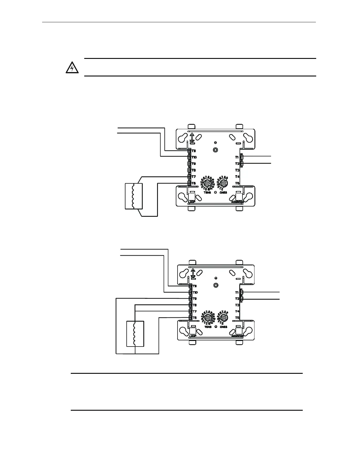
4.7.6 Connecting a Releasing Device to the FCM-1-REL
Typical Connections Figure 4.13 shows typical connections for wiring a releasing device to the
FCM-1-REL. Refer to the Device Compatibility Document for compatible releasing devices.
WARNING:
The XP6-C is not listed for releasing applications and cannot be substituted for FCM-1.
SLC (-)
SLC (+)
Non-resettable
24 VDC power
(-)
(+)
Compatible UL-listed
24 VDC releasing device.
One (1) device maximum.
Module polarities are shown in alarm condition.
All wiring shown is supervised and power-limited.
Figure 4.13 NPFA Style Y (Class B) Wiring of the FCM-1-REL
Compatible UL-listed
24 VDC releasing device.
One (1) device maximum.
Non-resettable
24 VDC power
SLC (-)
SLC (+)
(-)
(+)
Figure 4.13 NPFA Style Z (Class A) Wiring of the FCM-1-REL
Module polarities are shown in alarm condition.
All wiring shown is supervised and power-limited.
FCM-1-REL
FCM-1-REL
When using the FCM-1-REL for
Style Y (Class B) applications,
remove jumper J1.
fcm-1-rel-y.wmf
fcm-1-1rel-z.wmf
NOTE: With software version 12.0 or higher ALL new FlashScan Mode SLC releasing
applications require the FCM-1-REL control module. The V-type FCM-1 control module may be
used in SLC releasing applications with software version 12.0 or higher. H-type FCM-1 control
modules do not support FlashScan Mode releasing applications with software version 12.0 or
higher. Use H-type FCM-1 for CLIP mode releasing applications.

 Loading...


