44951501TH Rev.2
4-15
Oki Data CONFIDENTIAL
4.REPLACEMENT OF PARTS
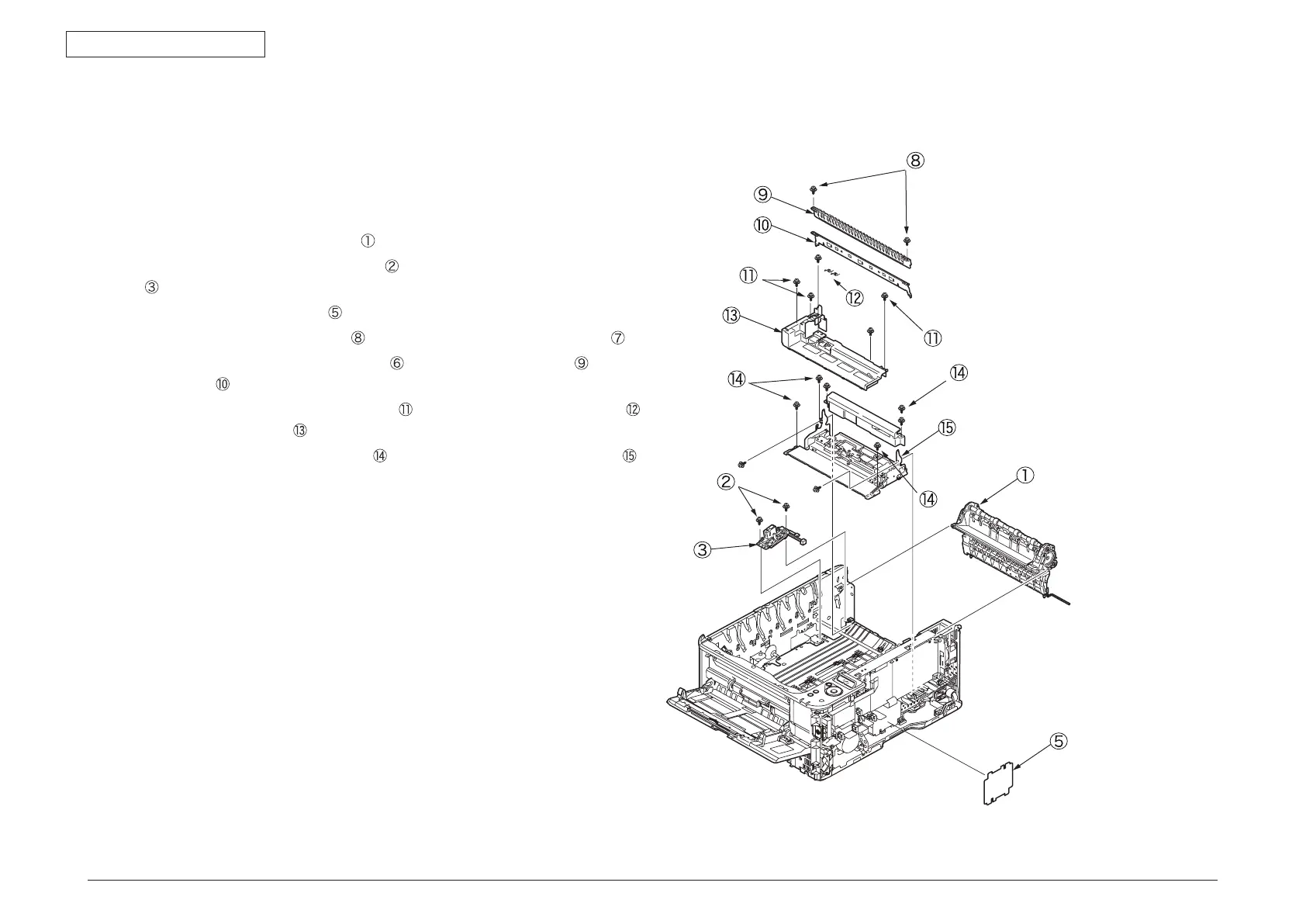
4.2.17 Guide-ejection assembly, fuser connector
assembly and color-registration assembly
(1) Remove the left side cover, the right side cover, the rear cover and the top cover
assembly.
(2) Remove the CU/PU PCB and the low-voltage power supply.
(3) Detach the guide-ejection assembly
.
(4) Remove the two (silver-colored) screws
to detach the fuser connector assembly
.
(5) Remove the film-power board
.
(6) Remove the (silver-colored) screw
to remove the image drum fan assembly .
(7) Remove the two (silver-colored) screws
to remove the cover-beam and the
plate-beam .
(8) Remove the three (silver-colored) screws
to remove the two torsion springs
and then the cover-code .
(9) Remove the four (silver-colored) screws
to detach the color-registration assembly .
 Loading...