EasyManuals Logo
Home>Omega>Thermometer>OS550A

Omega OS550A User Manual

Omega OS550A
77 pages
To Next Page IconTo Next Page
To Previous Page IconTo Previous Page
Page #24 background imageLoading...
Page #24 background image
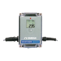
Figure 3-3. External Relay Wiring Diagram
Figure 3-4. Typical Transmitter Installation
3.3 Operating The Thermometer
1. After installing the thermometer (see section 2.1) and connection for
sensor cable and power/output (see section 3.2), your unit is ready
for use.
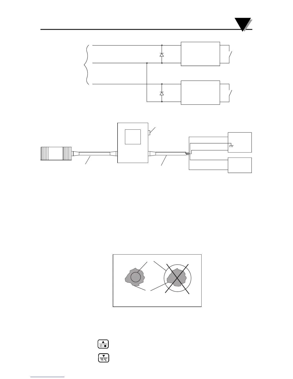
2. The optical field of view of the thermometers sensor head should fall
within the area of the target being measured. See Figure 3-2. Figures 3-
3 through 3-8 show the fields of view vs. distance for the various
thermometers.
Figure 3-5. Field of View Positions
3. The target temperature and emissivity are displayed on the LCD.
Determine the emissivity of the target (refer to Appendix B).
Press the key to increment the target emissivity.
Press the key to decrement the target emissivity
Field of View
Tar get
(ACCEPTABLE)
(UNACCEPTABLE)
YELLOW WIRE
OUTPUT
CABLE
BLACK OR GREEN WIRE
BLUE WIRE
HIGH ALARM
LOW ALARM
+
+
MECHANICAL
RELAY
8-24 VDC
MECHANICAL
RELAY
8-24 VDC
3-3
Using the Infrared Thermometer/Transmitter
3
SENSOR HEAD
SENSOR CABLE
POWER/OUTPUT
CABLE
8-24 VDC
POWER
SUPPLY
DIGITA L
VOLTMETER,
AMMETER,
RECORDER
(EARTH GND)
FIELD REPLACEABLE FUSE
(+ PWR) RED
+
+
(+ OUTPUT) WHITE
(– OUTPUT) GREEN
(– PWR) BLACK
SHIELD
OS550A
OS550AM
5 CONDUCTOR SHIELDED CABLE
8 CONDUCTOR SHIELDED CABLE

Table of Contents

Questions and Answers:

Question and Answer IconNeed help?

Do you have a question about the Omega OS550A and is the answer not in the manual?

Omega OS550A Specifications

General IconGeneral
BrandOmega
ModelOS550A
CategoryThermometer
LanguageEnglish

Related product manuals