Specifications
25
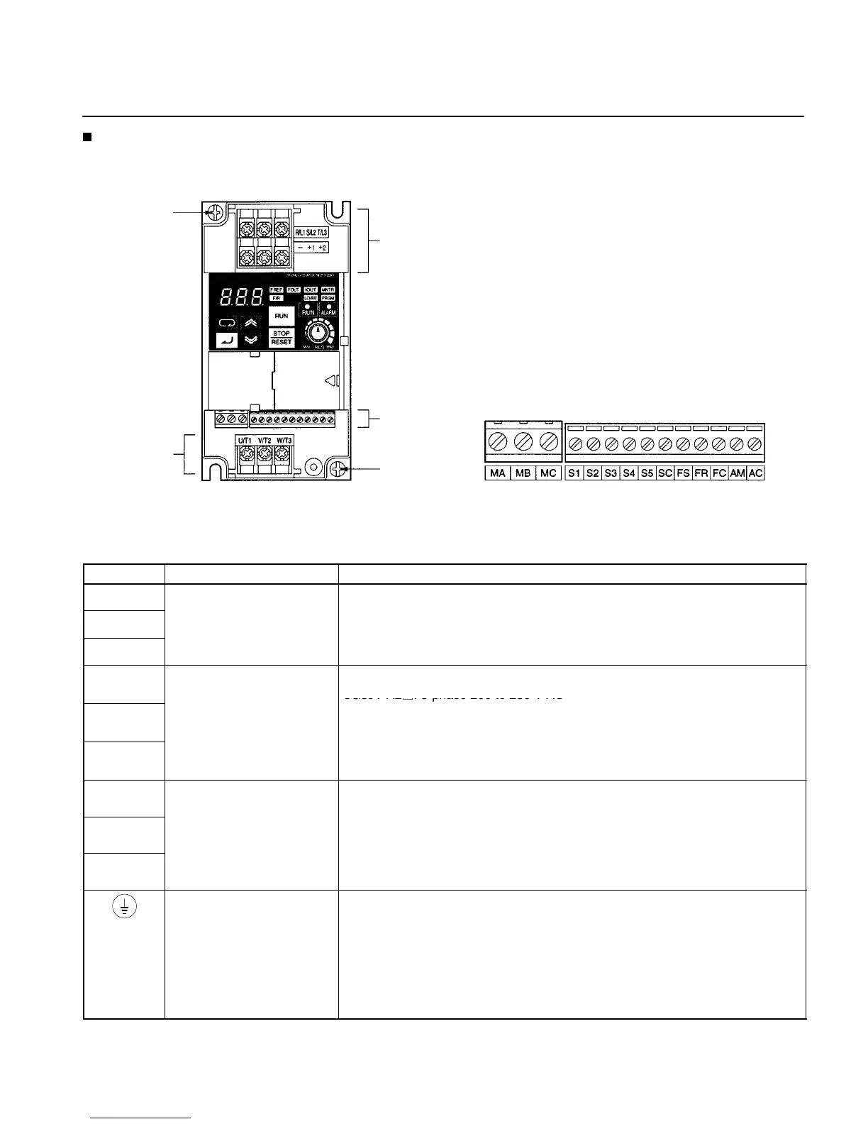
Terminal Block
Position of Terminal Block
Arrangement of Control Circuit Terminals
Ground terminal
Control circuit
terminals
Main circuit
output terminals
Main circuit input
terminals
Ground
terminal
Note: This illustration shows the terminal block with the front cover removed.
Main Circuit Terminals
Symbol Name Description
R/L1
Power supply input
3G3JV-A2j: 3-phase 200 to 230 V AC
3G3JV ABj Si l h 200 t 240 V AC
3G3JV-ABj: Single-phase 200 to 240 V AC
Note Connect single-phase input to terminals R/L1 and S/L2.
U/T1
Motor output terminals 3-phase power supply output for driving motors.
3G3JV-A2j: 3-phase 200 to 230 V AC
V/T2
3G3JV-ABj: 3-phase 200 to 240 V AC
3G3JV-A4j: 3-
Note The maximum output voltage corresponds to the input power supply
voltage for the Inverter.
+1
Connection terminals +1
and +2:
Connect the DC reactor for suppressing harmonics to terminals +1 and +2.
When driving the Inverter with DC power, input the DC power to terminals +1
+2
DC reactor connection
terminals
and –.
(Terminal +1 is a positive terminal.)
–
+
–:
DC power supply input
terminals
Ground terminal Be sure to ground the terminal under the following conditions.
3G3JV-A2j: Ground at a resistance of 100 Ω or less.
3G3JV-ABj: Ground at a resistance of 100 Ω or less.
3G3JV-A4j: Ground at a resistance of 10 Ω or less. Connect to a neutral point
on the power supply to conform to EC Directives.
Note Be sure to connect the ground terminal directly to the motor frame
ground.

 Loading...


