Specifications
26
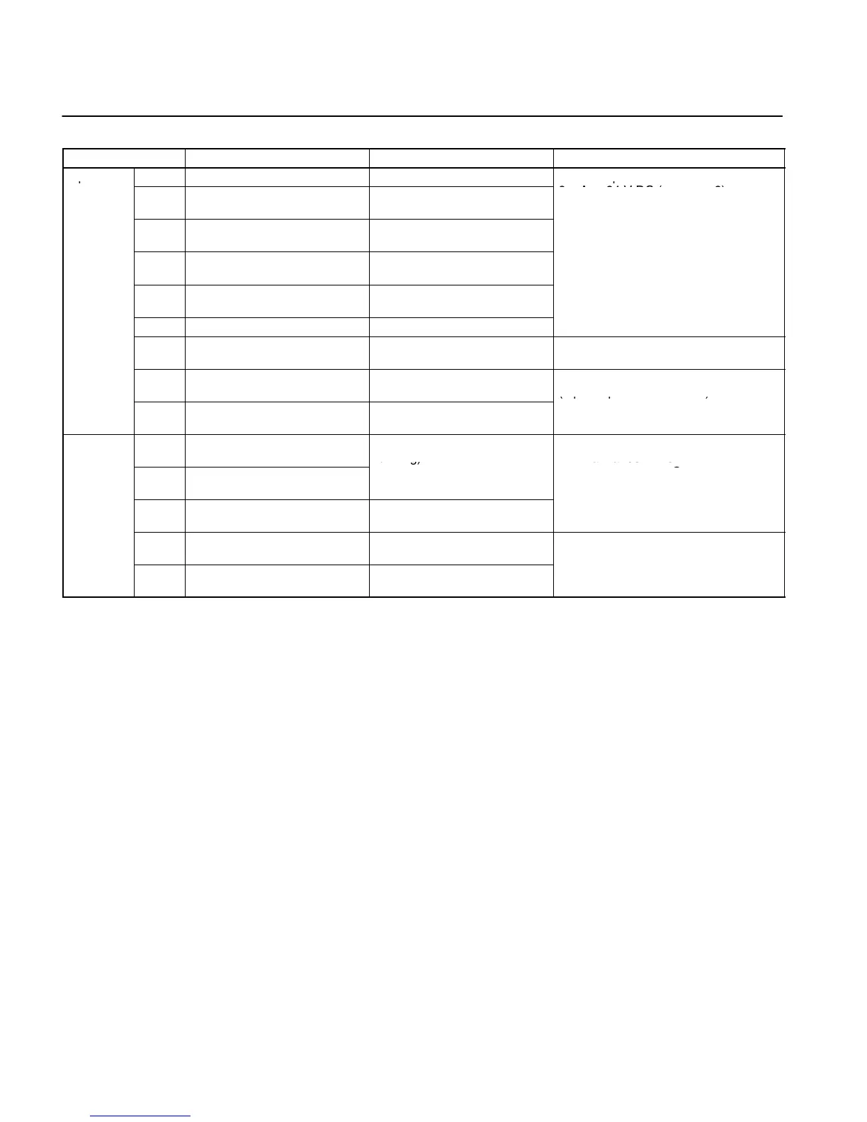
Control Circuit Terminals
Symbol Name Function Signal level
Input
S1 Forward/Stop Forward at ON. Stops at OFF.
Photocoupler
S2 Multi-function input 1 (S2) Set by parameter n36 (Re-
verse/Stop)
8 mA at 24 V DC (see note 2)
S3 Multi-function input 2 (S3) Set by parameter n37 (Fault
reset)
S4 Multi-function input 3 (S4) Set by parameter n38 (Exter-
nal fault: Normally open)
S5 Multi-function input 4 (S5) Set by parameter n39 (Multi-
step reference 1)
SC Sequence input common Common for S1 through S5
FS Frequency reference power
supply
DC power supply for frequen-
cy reference use
20 mA at 12 V DC
FR Frequency reference input Input terminal for frequency
reference use
0 to 10 V DC
(Input impedance = 20 kΩ)
FC Frequency reference common Common for frequency refer-
ence use
Output
MA Multi-function contact output
(Normally open)
Set by parameter n40 (during
running)
Relay output
1 A max. at 30 V DC
MB Multi-function contact output
(Normally closed)
1 A max. at 250 V AC
MC Multi-function contact output
common
Common for MA and MB use
AM Analog monitor output Set by parameter n44 (Output
frequency)
2 mA max. at 0 to 10 V DC
AC Analog monitor output com-
mon
Common for AM use
Note: 1. Functions in parentheses are default settings.
2. The input method is set to NPN by default, so use the GND common for wiring. An external power supply is not required.
When a power supply is used and a common on the plus side is used for wiring, set SW7 to PNP and use a 24-V DC (±10%)
power supply.
 Loading...


