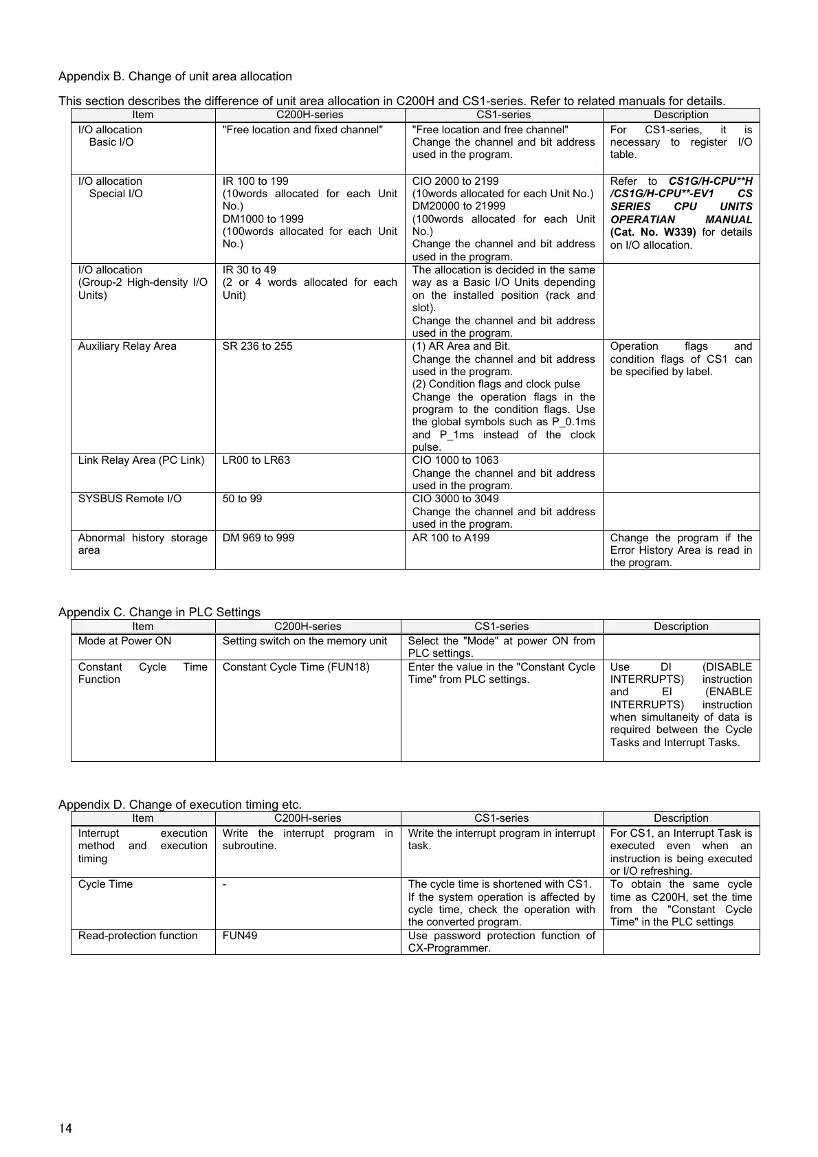
Appendix B. Change of unit area allocation
This section describes the difference of unit area allocation in C200H and CS1-series. Refer to related manuals for details.
Item C200H-series CS1-series Description
I/O allocation
Basic I/O
"Free location and fixed channel" "Free location and free channel"
Change the channel and bit address
used in the program.
For CS1-series, it is
necessary to register I/O
table.
I/O allocation
Special I/O
IR 100 to 199
(10words allocated for each Unit
No.)
DM1000 to 1999
(100words allocated for each Unit
No.)
CIO 2000 to 2199
(10words allocated for each Unit No.)
DM20000 to 21999
(100words allocated for each Unit
No.)
Change the channel and bit address
used in the program.
Refer to CS1G/H-CPU**H
/CS1G/H-CPU**-EV1 CS
SERIES CPU UNITS
OPERATIAN MANUAL
(Cat. No. W339) for details
on I/O allocation.
I/O allocation
(Group-2 High-density I/O
Units)
IR 30 to 49
(2 or 4 words allocated for each
Unit)
The allocation is decided in the same
way as a Basic I/O Units depending
on the installed position (rack and
slot).
Change the channel and bit address
used in the program.
Auxiliary Relay Area SR 236 to 255 (1) AR Area and Bit.
Change the channel and bit address
used in the program.
(2) Condition flags and clock pulse
Change the operation flags in the
program to the condition flags. Use
the global symbols such as P_0.1ms
and P_1ms instead of the clock
pulse.
Operation flags and
condition flags of CS1 can
be specified by label.
Link Relay Area (PC Link) LR00 to LR63 CIO 1000 to 1063
Change the channel and bit address
used in the program.
SYSBUS Remote I/O 50 to 99 CIO 3000 to 3049
Change the channel and bit address
used in the program.
Abnormal history storage
area
DM 969 to 999 AR 100 to A199 Change the program if the
Error History Area is read in
the program.
Appendix C. Change in PLC Settings
Item C200H-series CS1-series Description
Mode at Power ON Setting switch on the memory unit Select the "Mode" at power ON from
PLC settings.
Constant Cycle Time
Function
Constant Cycle Time (FUN18) Enter the value in the "Constant Cycle
Time" from PLC settings.
Use DI (DISABLE
INTERRUPTS) instruction
and EI (ENABLE
INTERRUPTS) instruction
when simultaneity of data is
required between the Cycle
Tasks and Interrupt Tasks.
Appendix D. Change of execution timing etc.
Item C200H-series CS1-series Description
Interrupt execution
method and execution
timing
Write the interrupt program in
subroutine.
Write the interrupt program in interrupt
task.
For CS1, an Interrupt Task is
executed even when an
instruction is being executed
or I/O refreshing.
Cycle Time - The cycle time is shortened with CS1.
If the system operation is affected by
cycle time, check the operation with
the converted program.
To obtain the same cycle
time as C200H, set the time
from the "Constant Cycle
Time" in the PLC settings
Read-protection function FUN49 Use password protection function of
CX-Programmer.

 Loading...


