87
5-2 Inspection and Maintenance
5-2-1 Replacing Output Unit Fuses
The following Output Units each contain one fuse. Replace the fuse if the fuse
indicator lights. The OD211, OD212, OA222, and OA224 Output Units do not
have fuse indicators. Replace the fuses on these Units if outputs are not pro-
duced.
Unit Fuse indicator Capacity
(20 mm long x 5.2 mm dia.)
C200H-OD411 Yes
125 V, 5 A
C200H-OD211 No
C200H-OD212 No
125 V, 8 A
C200H-OD213 Yes
C200H-OA221 Yes 250 V, 5 A
C200H-OA222V No 250 V, 3 A
C200H-OA223 Yes 250 V, 5 A
C200H-OA224 No 250 V, 3.15 A
The OD411, OD213, OA221 and OA223 Output Units also provide an external
output bit that can be used to check the condition of the fuse. If bit 08 of the word
allocated to the Unit is ON, the fuse is burnt out.
To replace a fuse, follow the steps below. Use only UL/CSA certified replace-
ment fuses.
1, 2, 3... 1. Turn OFF the power to the PC.
2. Detach the terminal block by unlocking the lock levers at the top and bottom
of the terminal block.
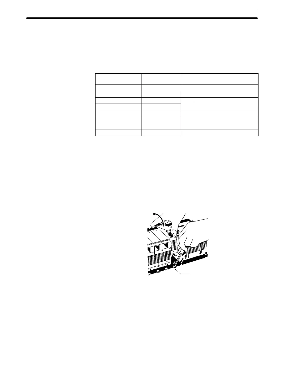
3. While pushing down the lock lever on the Backplane with a screwdriver as
shown below, remove the Output Unit.
Lock lever
Inspection and Maintenance
Section 5-2
 Loading...


