3
E3MCE3MC
Specifications
■ Ratings/Characteristics
Item Built-in amplifier type Optical fiber type General-purpose optical fiber
type
E3MC-A@1, E3MC-MA@1E3MC-X@1, E3MC-MX@1E3MC-Y@1, E3MC-MY@1
Light source Red (680 nm), green (525 nm), and blue (450 nm) LEDs
Sensing distance 60±10 mm (see note 1) 20±4 mm (see note 1) Varies with the recommended fiber.
Refer to page 5 for details.
Spot diameter 12 dia. 3 dia. ---
Supply voltage 12 to 24 VDC±10%, ripple (p-p) 10% max.
Current consumption 100 mA max.
Discriminating color
registration
Possible to register four colors in teaching operation with manual threshold level adjustments.
Control output Load current: 100 mA max.
NPN open collector output with a maximum residual voltage of 1.2 V for the E3MC-(M)A11, E3MC-(M)X11, and
E3MC-(M)Y11.
PNP open collector output with a maximum residual voltage of 2.0 V for the E3MC-(M)A41, E3MC-(M)X41, and
E3MC-(M)Y41.
Color discrimination
mode
Response time 1-output model:
Standard mode: 3 ms max.
High-speed mode: 1 ms max. (switch selectable)
4-output model:
Standard mode: 6 ms max.
High-speed mode: 2 ms max. (switch selectable)
Timer function 40-ms OFF-delay timer (ON/OFF switch selectable)
Output type Conformity output: Output is ON when the detected color coincides with the registered color.
Non-conformity output: Output is ON when the detected color does not coincide with the registered color.
(switch selectable)
Mode selection
Remote control input
(see note 6)
(mode B only)
The following control is performed according to the control signal input.
E3MC-@11/-@41
Bank selection, remote teaching, or threshold selection
E3MC-M@11/-M@41
Channel selection, remote teaching, or threshold selection
Answer-back output
(see note 6)
(mode B only)
Load current: 100 mA max.
NPN open collector output with a residual voltage of 1.2 V max.
E3MC-(M)A11/-(M)X11/-(M)Y11
PNP open collector output with a residual voltage of 2.0 V max.
E3MC-(M)A41/-(M)X41/-(M)Y41
External synchronous
input
Response time: 1 ms max. (The 4-output model is not available in mode B.)
Mode C: RGB ratio detection
Mode I: RGB li
ht intensit
detection
Switch selectable
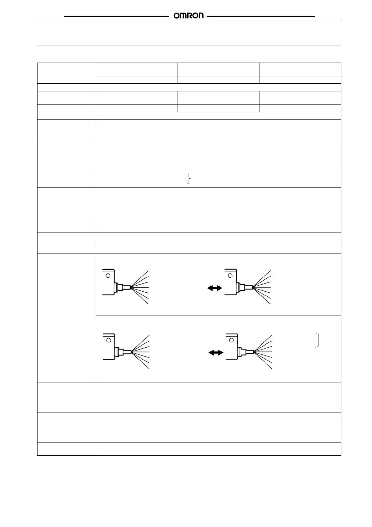
E3MC-@11/-@41
Mode A (Factory-set) Mode B (for remote teaching)
Control output (white)
Not used (gray)
Bank selection input 1 (yellow)
Bank selection input 2 (green)
External synchronous input (pink)
V
CC
(brown)
0 V (blue)
Colors in parentheses are lead wire colors.
Control output (white)
Answer-back output (gray)
Remote control input (yellow)
Not used
External synchronous input (pink)
V
CC
(brown)
0 V (blue)
Colors in parentheses are lead wire colors.
E3MC-M@11/-@M41
Mode A (Factory-set)
Mode B (for remote teaching)
Control output 1 (white)
Control output 2 (gray)
Control output 3 (yellow)
Control output 4 (green)
External synchronous input (pink)
V
CC
(brown)
0 V (blue)
Colors in
arentheses are lead wire colors.
Control output 1 (white)
Control output 2 (gray)
Control output 3 (yellow)
V
CC
(brown)
0 V (blue)
Colors in
arentheses are lead wire colors.
Answer-back output (green)
Remote control input (pink)
3 output
 Loading...