8
E3MCE3MC
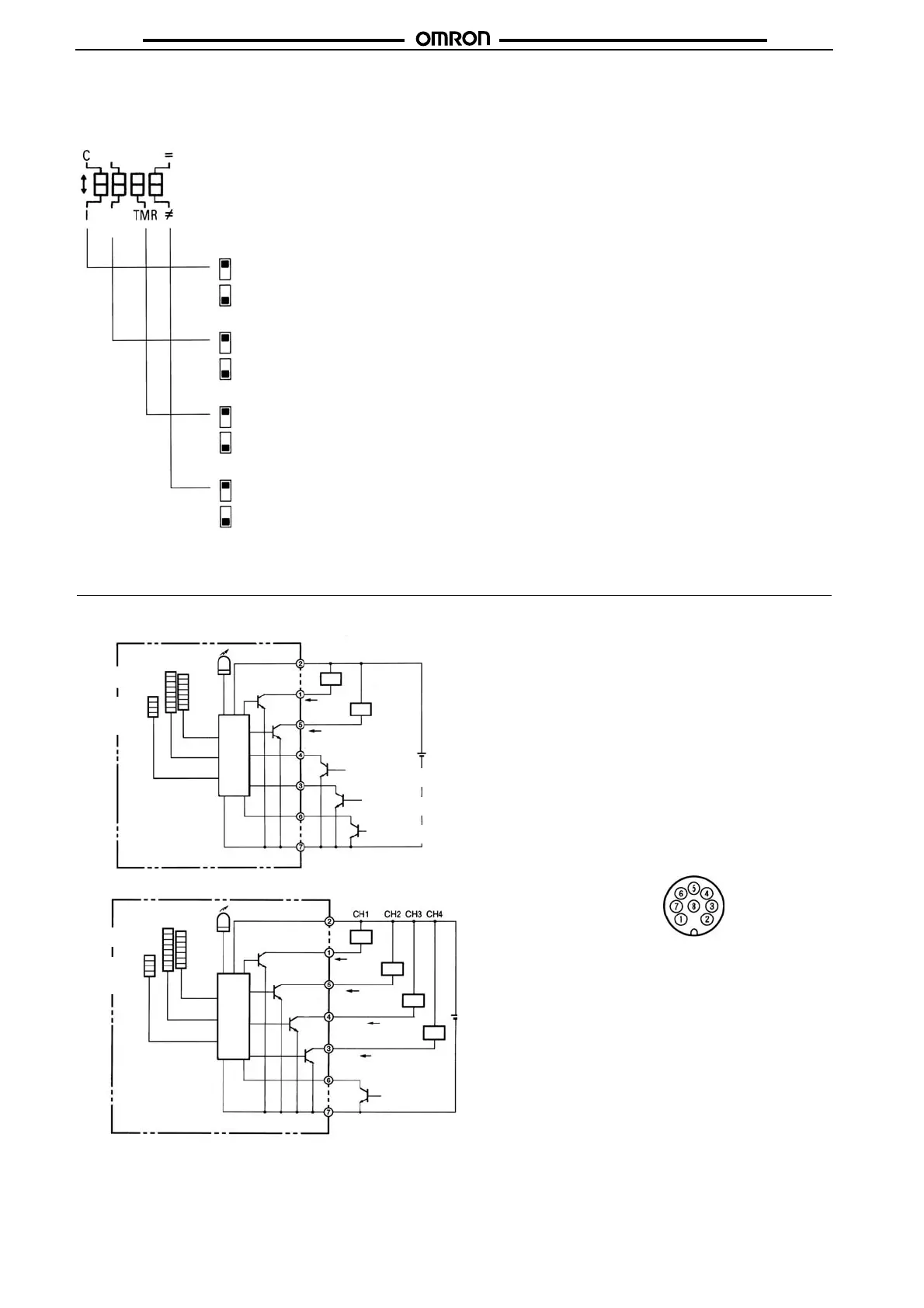
*Function Switch
The following settings are possible in RUN or ADJ mode. In case of 4-output models, all channels are subject to the selection of the follow-
ing settings. Each pin of the function switch is factory-set to the upper position.
Operation
■ Output Circuits
Color Discrimination Mode Selection (Mode C is Recommended for Normal Applications)
Response Time Selection (Note: Figures in parentheses are for the 4-output models.)
OFF-delay Timer Setting
---: No OFF-delay timer is set.
TMR: A 40-ms OFF-delay timer is set for control output.
Conformity/Non-conformity Output
=: Output is ON when the detected color coincides with the registered color.
≠: Output is ON when the detected color does not coincide with the registered color.
Note: Figures in parentheses are for the 4-output models.
1 ms
(2 ms)
(6 ms)
3 ms
Note: Each
in of the function switch is factor
-set to the u
er
osition.
Mode C: Color discrimination is performed according to R (red), G (green), and B (blue) ratio of the
reflection light even if the sensing objects fluctuate up and down within the rated sensing range.
Mode I: Color discrimination is performed according to RGB light intensity of reflection light.
This mode ensures more delicate color discrimination than mode C.
3 ms (6 ms): The E3MC can stably detect minute differences of color. Set the
response time to 3 ms for usual applications.
1 ms (2 ms): The E3MC will be in quick-response operation. Set the
response time to 1 ms if high-speed response is required.
E3MC-@11 with NPN Output (1-output Models)
Connector Pin Arrangement
Brown
White
Ye l l o w
Green
Pink
Blue
Load
12 to 24 VDC
E3MC-M@11 with NPN Output (4-output Models)
12 to 24 VDC
Load
Brown
White
Ye l l o w
Gray
Green
Pink
Blue
Gray
Load
Note: Pin 8 is not used.
Load
Load
Load
8-level detection
indicator (green)
4-level
bank
indicator
(green)
Main
circuit
Main
circuit
8-level detection
indicator (green)
4-level
bank
indicator
(orange)
Operation indicator
(orange)
Operation indicator
(orange)
7-level
threshold
indicator
(red)
7-level
threshold
indicator
(red)
Control
output
Control
output
Control
output
Control
output
Not used/Answer-
back output
Bank selection input 1/
Remote control input
Bank selection input 2/
Not used
External synchronous
input
External
synchronous
input/Remote
control input
Control output/
Answer back output
 Loading...