E5CD-800
12
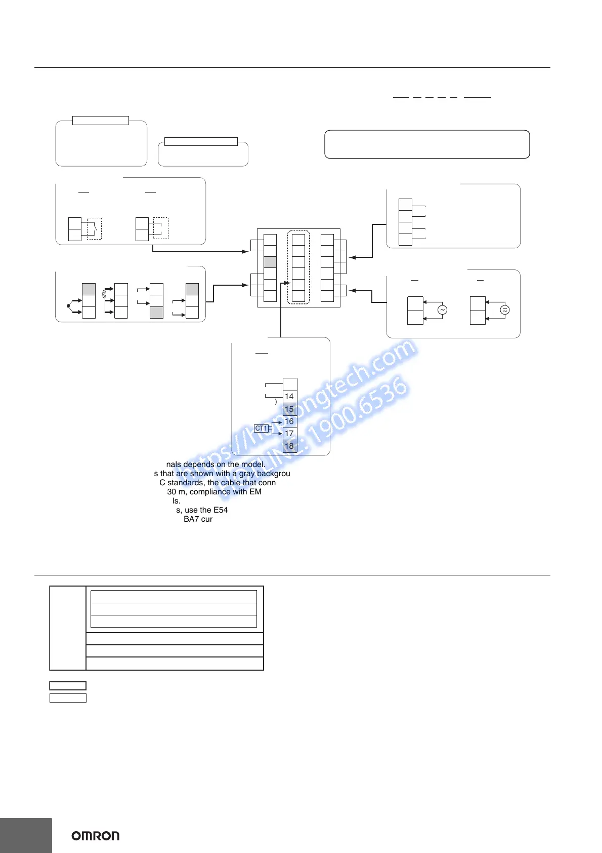
External Connections
E5CD-800
Note: 1. The application of the terminals depends on the model.
2. Do not wire the terminals that are shown with a gray background.
3. When complying with EMC standards, the cable that connects the sensor must be 30 m or less.
If the cable length exceeds 30 m, compliance with EMC standards will not be possible.
4. Connect M3 crimped terminals.
5. Due to UL Listing requirements, use the E54-CT1L or E54-CT3L Current Transformer with the factory wiring (internal wiring).
Use a UL category XOBA or XOBA7 current transformer that is UL Listed for field wiring (external wiring) and not the factory wiring
(internal wiring).
Isolation/Insulation Block Diagrams
A
−
+
5
4
V
−
5
V
6
+
4
TC
4
I
10
7
8
9
18
13
14
15
16
17
CT1
B(+)
A(
−
)
RS-485
17
18 12
15
16
1
2
13
14
3
11
4
6
7
8
9
10
5
The E5CD-800 is set for a K-type thermocouple (input type = 5) by
default. An input error (s.err) will occur if the input type setting does
not agree with the temperature sensor. Check the input type.
Relay output
250 VAC, 3 A (resistive load)
Voltage output
(for driving SSR)
12 VDC, 21 mA
Relay outputs
250 VAC, 3 A (resistive load)
(no polarity)
100 to 240 VAC 24 VAC/DC
Auxiliary outputs 1, 2
Auxiliary output 2
Auxiliary output 1
802
Communications
(RS-485), CT1
(2) Auxiliary Outputs
(3) Input Power Supply
(5) Sensor (Temperature/Analog) Input
(6) Options
Models with
1 Relay Output
(1) Control output 1
Models with 1
Voltage Output
(for Driving SSR)
E5CD-@@ 2 @ D M - @@@
↑
Terminal type
11
12
11
12
(1) (2) (3) (4) (5) (6)
Control output 1
Auxiliary outputs 1, 2
OUT1
R
1
2
RX
1
2
OUT1
Q
QX
+
−
A
D
Sensor input and CT input
Communications
Voltage output (for driving SSR)
Relay output
Auxiliary output 1
: Reinforced insulation
: Functional isolation
Power
supply
Auxiliary output 2
 Loading...